Getting Started with ADC on STM32F103C8 (Blue Pill) using Rust
Microcontrollers are often used to measure input voltage levels rather than just reading HIGH and LOW states. For instance, when working with a moisture sensor, measuring the moisture level requires using an Analog Input to convert the voltage input into a digital value, which is then calculated to determine the percentage of moisture. If you use a standard digital input as discussed in the previous article, you will only obtain HIGH and LOW values without knowing the actual moisture level.
Introduction to Analog to Digital Converter (ADC) on STM32F103C8
The STM32F103C8 features 10 pins that can be configured as analog inputs—specifically pins PA0-PA7 and PB0-PB1—with a maximum acceptable voltage of 3.3V. When an STM32F103C8 pin is configured as an analog input, it connects to the Analog to Digital Converter (ADC) peripheral, which converts the input voltage into a digital value. The STM32F103C8 is equipped with 2 ADC units (ADC1 and ADC2) featuring a 12-bit resolution (0-4095) and a precision of approximately 0.8mV (an input voltage change of 0.8mV will cause a digital value change of 1). The ADC frequency of the STM32F103C8 can be configured up to 14MHz.
Modes and Features of the ADC STM32F103C8
The STM32F103C8 ADC can operate in 4 distinct modes:
- Single conversion mode: The ADC performs a single conversion on the selected channel and then stops. This mode is typically used when reading sensors whose values do not change rapidly (such as temperature or humidity sensors).
- Scan mode: The ADC scans and converts a predefined list of multiple channels sequentially, one by one, before stopping. Scan mode is commonly combined with DMA (Direct Memory Access) to prevent data from being overwritten in the same register. This mode is used to monitor multiple sensors simultaneously and synchronously.
- Continuous conversion mode: The ADC automatically converts data continuously and repeatedly without waiting for further CPU commands. In single-channel operation, the ADC automatically restarts conversion as soon as the current one finishes. In multi-channel operation, it cycles back to the first channel and converts through the sequence continuously.
- Discontinuous conversion mode: This mode divides a group of channels into smaller subgroups within Scan Mode. The ADC converts from the first channel of the first subgroup to the last channel of the final subgroup, setting the
eoc(End of Conversion) register bit to 1 at the end of each subgroup conversion.
The advanced features of the STM32F103C8 ADC include:
- Simultaneous sample and hold: Utilizes two ADC units simultaneously (in parallel). This allows it to sample two different channels (channel 1 to ADC1 and channel 2 to ADC2) at the exact same instant.
- Interleaved sample and hold: The ADC1 and ADC2 units work alternately to read and convert a single channel. This mode effectively doubles the ADC sampling rate, making it ideal for high-frequency signal reading.
- Single shunt: Reads and converts a channel with a very low input voltage (in the millivolt range). This is typically used for current monitoring by measuring the voltage drop across a shunt resistor.
ADC Peripheral Support on STM32F103C8
The STM32F103C8 ADC can also be integrated with other peripherals, such as:
- ADC with DMA (Direct Memory Access): The ADC transfers the conversion results directly to the RAM without CPU intervention, thereby reducing CPU overhead. The CPU only needs to read the data from the RAM once the conversion process is complete.
- ADC with Analog Watchdog: The ADC conversion values are monitored by the Analog Watchdog. If the value falls outside the predefined upper or lower thresholds, the Analog Watchdog triggers an interrupt.
- ADC with Timer: The ADC performs conversions at precise periodic intervals based on a configured Timer.
Hardware Preparation
The hardware used in this tutorial is almost identical to the hardware used in the previous article. While the previous article utilized a push button, this tutorial will use a potentiometer to adjust the input voltage level to the STM32F103C8 GPIO pin.
Potentiometer
A potentiometer is a three-pin variable resistor. Unlike a standard resistor that has a fixed resistance value, the resistance of a potentiometer can be adjusted manually by turning its knob. This tutorial will use a potentiometer with a resistance value of 5kΩ.
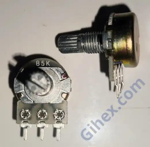
Pro Tip: A 5kΩ value is ideal for this experiment as it provides a stable voltage divider without drawing excessive current from the STM32F103C8’s 3.3V rail. The middle pin will output a variable voltage between 0V and 3.3V, which the ADC then converts into a digital value ranging from 0 to 4095.
Using Analog Input on Blue Pill(STM32F103C8) with Rust
This tutorial will focus on how to use the ADC in single conversion mode. The use of continuous conversion, scan mode, and other advanced features of the STM32F103C8 ADC will be covered in detail in subsequent articles.
There are several methods available for utilizing the Blue Pill’s ADC, including the Poll, Direct Memory Access (DMA), and Interrupt methods. The following are the variations of single conversion mode on the STM32F103C8 ADC:
- Single conversion Poll: The ADC only performs a conversion when commanded by the CPU, and the CPU waits for the conversion process to complete before reading the result. After that, the ADC will not perform another conversion until it receives another command from the CPU. This method is suitable when you do not need to read the sensor frequently or only need to sample it at specific times.
- Single conversion DMA: The ADC performs a conversion when commanded by the CPU, and the conversion result is automatically transferred directly to the RAM (DMA buffer). During the conversion process, the CPU can execute other tasks. Once the DMA buffer is populated, the CPU reads the result from it. Following this, the ADC idles until the next CPU command. When properly configured, this method significantly reduces CPU overhead, making it ideal for reading sensors rapidly and continuously.
- Single conversion Interrupt: The ADC performs a conversion when commanded by the CPU. Once the conversion is complete, the ADC signals the CPU, causing it to temporarily pause its main program execution to run the ISR (Interrupt Service Routine). Afterward, the ADC stops until commanded again. If too many conversions are triggered per second using this method, the CPU will be overwhelmed by constant interrupts, which increases CPU overhead. Consequently, this method is typically reserved for reading critical or emergency sensors.
In this tutorial, we will read the input voltage level from a potentiometer and display its corresponding digital value on a PC/laptop terminal. This tutorial will utilize GPIO pin PA0 as the analog input.
Blue Pill (STM32F103C8) and Potentiometer Circuit
The potentiometer is used as a voltage divider device that will act like a sensor. Let’s gather the necessary components and start building the circuit according to the following schematic diagram:
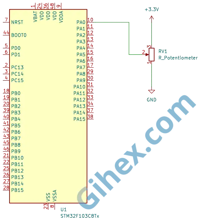
According to the schematic diagram, the voltage level received by pin PA0 will change as the potentiometer is turned, which in turn changes the digital value. When the potentiometer knob is turned toward GND, the resistance between pin PA0 and GND decreases, while the resistance between pin PA0 and 3.3V increases; thus, the voltage entering pin PA0 becomes lower. Conversely, when the knob is turned toward 3.3V, the resistance between pin PA0 and GND increases, while the resistance between pin PA0 and 3.3V decreases, causing the voltage entering pin PA0 to become higher.
Programming the Blue Pill (STM32F103C8) as an Analog Input with Single Conversion Poll
Please create a new Rust project and configure it according to the Setting up the STM32F103C8 with Rust article. Open the Cargo.toml file and add the following code to define a new binary named ‘single-conversion-poll’:
1[[bin]]
2name = "single-conversion-poll"
3path = "src/main.rs"
4test = false
5bench = false
Next, open the src/main.rs file and insert the following code (as usual, the functional explanation for each line is provided as comments):
 1#![no_std]
 2#![no_main]
 3
 4use defmt_rtt as _;
 5use panic_probe as _;
 6
 7use cortex_m::delay::Delay;
 8use cortex_m_rt::entry;
 9use stm32f1xx_hal::{
10    adc,
11    flash::FlashExt,
12    gpio::GpioExt,
13    pac,
14    prelude::*,
15    rcc::{Config, RccExt},
16    time::Hertz,
17};
18
19#[entry]
20fn main() -> ! {
21    defmt::println!("STM32F103C8 Access GPIO as Analog Input Single Conversion Poll");
22
23    // Access STM32F103C8 peripherals
24    let dp = pac::Peripherals::take().unwrap();
25
26    // Access STM32F103C8 core peripherals (Cortex-M3)
27    let cp = pac::CorePeripherals::take().unwrap();
28
29    // Access FLASH peripheral to adjust 'wait states' during Clock configuration
30    let mut flash = dp.FLASH.constrain();
31
32    // Access Reset & Control Clock (RCC) peripheral for configuration
33    let rcc = dp.RCC.constrain();
34
35    // Create Reset & Control Clock (RCC) configuration
36    let clock_config = Config::default()
37        .use_hse(Hertz::MHz(8)) // Use 8MHz external crystal oscillator (HSE)
38        .sysclk(Hertz::MHz(72)) // Set CPU frequency to 72MHz
39        .hclk(Hertz::MHz(72)) // Set BUS frequency (SRAM and FLASH access path) to 72MHz
40        .adcclk(Hertz::MHz(9)); // Set ADC frequency to 9MHz
41
42    // Apply clock configuration to RCC and adjust flash memory wait states
43    let mut clocks = rcc.freeze(clock_config, &mut flash.acr);
44
45    // Create a delay instance using the Cortex-M3 System Timer (SYST)
46    let mut delay = Delay::new(cp.SYST, clocks.clocks.hclk().to_Hz());
47
48    // Access ADC1 peripheral
49    let mut adc1 = adc::Adc::new(dp.ADC1, &mut clocks);
50
51    // Access GPIO Port A peripheral
52    let mut gpioa = dp.GPIOA.split(&mut clocks);
53    // Configure PA0 as an analog input
54    let mut potentio = gpioa.pa0.into_analog(&mut gpioa.crl);
55
56    // The program will run repeatedly in an infinite loop
57    loop {
58        // CPU commands ADC1 to read and convert the input voltage into a digital value
59        let data: u16 = adc1.read(&mut potentio).unwrap();
60        // Calculate the input voltage from the read digital value
61        let voltage_input = 3.3f32 * data as f32 / 4095.0f32;
62        // Send message to PC/laptop
63        defmt::println!(
64            "Digital value: {} || voltage input: {}V",
65            data,
66            voltage_input
67        );
68        // Wait for 200 ms
69        delay.delay_ms(200);
70    }
71}
Connect the ST-Link to your PC/laptop, then execute the Rust code by running the ‘cargo run --bin single-conversion-poll’ command in the VSCode terminal. Try turning the potentiometer knob; the analog input reading results will appear in the terminal. The following are the results of the single conversion poll analog input experiment:
Programming the Blue Pill (STM32F103C8) as Input Analog with Single Conversion DMA
Pada STM32F103C8 hanya ADC1 yang bisa digunakan dengan DMA, sedangkan ADC2 tidak bisa. DMA harus diinisialisasi terlebih dahulu sebelum digunakan, dan penjelasan detail mengenai DMA (Direct Memory Access) akan dibahas pada artikel berikutnya.
Note: For ADC1, the only DMA channel that can be used is Channel 1; if you connect it to another channel, the program will not function.
Let’s start, on Cargo.toml file, add the following code to define a new binary:
1[[bin]]
2name = "single-conversion-dma"
3path = "src/single_conversion_dma.rs"
4test = false
5bench = false
Next, create the src/single_conversion_dma.rs file, and insert the following code:
 1#![no_std]
 2#![no_main]
 3
 4use cortex_m::delay;
 5use defmt_rtt as _;
 6use panic_probe as _;
 7
 8use cortex_m_rt::entry;
 9use stm32f1xx_hal::{adc, pac, prelude::*, rcc::Config, time::Hertz};
10
11#[entry]
12fn main() -> ! {
13    defmt::println!("STM32F103C8 Access GPIO as Analog Input Single Conversion DMA");
14
15    // Access STM32F103C8 peripherals
16    let dp = pac::Peripherals::take().unwrap();
17
18    // Access STM32F103C8 core peripherals (Cortex-M3)
19    let cp = pac::CorePeripherals::take().unwrap();
20
21    // Access FLASH peripheral to adjust 'wait states' during Clock configuration
22    let mut flash = dp.FLASH.constrain();
23
24    // Access Reset & Control Clock (RCC) peripheral for configuration
25    let rcc = dp.RCC.constrain();
26
27    // Create Reset & Control Clock (RCC) configuration
28    let clock_config = Config::default()
29        // Use 8MHz external crystal oscillator (HSE)
30        .use_hse(Hertz::MHz(8))
31        // Set CPU frequency to 72MHz
32        .sysclk(Hertz::MHz(72))
33        // Set BUS frequency (SRAM and FLASH access path) to 72MHz
34        .hclk(Hertz::MHz(72))
35        // Set ADC frequency to 9MHz
36        .adcclk(Hertz::MHz(9));
37
38    // Apply clock configuration to RCC and adjust flash memory wait states
39    let mut clocks = rcc.freeze(clock_config, &mut flash.acr);
40
41    // Create a delay instance using the Cortex-M3 System Timer (SYST)
42    let mut delay = delay::Delay::new(cp.SYST, clocks.clocks.hclk().to_Hz());
43
44    // Initialize ADC1 peripheral
45    let adc1 = adc::Adc::new(dp.ADC1, &mut clocks);
46
47    // Configure GPIO PA0 as Analog Input
48    let mut gpioa = dp.GPIOA.split(&mut clocks);
49    let potentio = gpioa.pa0.into_analog(&mut gpioa.crl);
50
51    // Initialize DMA1
52    let dma1_channels = dp.DMA1.split(&mut clocks);
53
54    // Link ADC with DMA Channel 1
55    let mut adc_dma = adc1.with_dma(potentio, dma1_channels.1);
56
57    // Prepare Buffer to be filled by DMA
58    // (Example: taking 10 samples for averaging)
59    let mut buffer = cortex_m::singleton!(: [u16; 10] = [0; 10]).unwrap();
60
61    loop {
62        // CPU commands ADC to convert and use DMA to store data in the buffer
63        let transfer = adc_dma.read(buffer);
64
65        // Read conversion results from the DMA buffer
66        let (recovered_buffer, recovered_adc_dma) = transfer.wait();
67
68        // Process data (average 10 samples) and calculate voltage
69        // from the digital values read
70        let sum: u32 = recovered_buffer.iter().map(|&v| v as u32).sum();
71        let avg = (sum / recovered_buffer.len() as u32) as u16;
72        let voltage = (avg as f32 / 4095.0) * 3.3;
73
74        // Send message to PC/laptop
75        defmt::println!("Raw Avg: {} | Volt: {}V", avg, voltage);
76
77        // Return buffer and adc variables to be reused in the next loop iteration
78        adc_dma = recovered_adc_dma;
79        buffer = recovered_buffer;
80
81        // Wait for 200ms
82        delay.delay_ms(200);
83    }
84}
Execute the Rust code by running the command ‘cargo run --bin single-conversion-dma’ in the VSCode terminal, then try turning the potentiometer knob. The following are the results of the single conversion DMA analog input experiment:
Programming the Blue Pill (STM32F103C8) as Input Analog with Single Conversion Interrupt
Since the stm32f1xx_hal crate does not provide methods for reading the ADC via interrupts, the ADC configuration must be handled at a lower level by directly accessing the ADC registers. This program will be kept as simple as possible to ensure it is easy to understand. A detailed explanation regarding interrupts will be covered in a subsequent article.
First, lets define new binary. Open the Cargo.toml file and add the following code:
1[[bin]]
2name = "single-conversion-interrupt"
3path = "src/single_conversion_interrupt.rs"
4test = false
5bench = false
Next, create the src/single_conversion_interrupt.rs file, and insert the following code:
  1#![no_std]
  2#![no_main]
  3
  4use core::sync::atomic::AtomicI16;
  5use core::sync::atomic::Ordering;
  6
  7use cortex_m::delay;
  8use defmt_rtt as _;
  9use panic_probe as _;
 10
 11use cortex_m_rt::entry;
 12use stm32f1xx_hal::adc::SampleTime;
 13use stm32f1xx_hal::gpio::PinExt;
 14use stm32f1xx_hal::pac::Interrupt;
 15use stm32f1xx_hal::pac::interrupt;
 16use stm32f1xx_hal::{adc, pac, prelude::*, rcc::Config, time::Hertz};
 17
 18// Global variable to store the ADC value. Uses an atomic type to prevent
 19// race conditions when data is modified in the interrupt and read in the main loop.
 20static ADC_VALUE: AtomicI16 = AtomicI16::new(0);
 21
 22#[entry]
 23fn main() -> ! {
 24    defmt::println!("STM32F103C8 Access GPIO as Analog Input Single Conversion Interrupt");
 25
 26    // Accessing STM32F103C8 peripherals
 27    let dp = pac::Peripherals::take().unwrap();
 28
 29    // Accessing STM32F103C8 core peripherals (Cortex-M3)
 30    let cp = pac::CorePeripherals::take().unwrap();
 31
 32    // Accessing FLASH peripheral to adjust 'wait states' during Clock configuration.
 33    let mut flash = dp.FLASH.constrain();
 34
 35    // Accessing Reset & Control Clock (RCC) peripheral for configuration
 36    let rcc = dp.RCC.constrain();
 37
 38    // Creating Reset & Control Clock (RCC) configuration
 39    let clock_config = Config::default()
 40        // Use 8MHz external crystal oscillator (HSE)
 41        .use_hse(Hertz::MHz(8))
 42        // Set CPU frequency to 72MHz
 43        .sysclk(Hertz::MHz(72))
 44        // Set BUS frequency (SRAM and FLASH access path) to 72MHz
 45        .hclk(Hertz::MHz(72))
 46        // Set ADC frequency to 9MHz
 47        .adcclk(Hertz::MHz(9));
 48
 49    // Apply clock configuration to RCC and adjust flash memory wait states
 50    let mut clocks = rcc.freeze(clock_config, &mut flash.acr);
 51
 52    // Create a delay instance using the Cortex-M3 System Timer (SYST).
 53    let mut delay = delay::Delay::new(cp.SYST, clocks.clocks.hclk().to_Hz());
 54
 55    // Initialize ADC1 peripheral
 56    let mut adc1 = adc::Adc::new(dp.ADC1, &mut clocks);
 57
 58    // Enable End of Conversion (EOC) interrupt on ADC1
 59    adc1.enable_eoc_interrupt();
 60
 61    // Configure GPIO PA0 as Analog Input
 62    let mut gpioa = dp.GPIOA.split(&mut clocks);
 63    let potentio = gpioa.pa0.into_analog(&mut gpioa.crl);
 64
 65    // Set ADC sample time for channel PA0 to default
 66    adc1.set_channel_sample_time(potentio.pin_id(), SampleTime::default());
 67
 68    // Enable ADC1_2 interrupts in the NVIC.
 69    unsafe {
 70        pac::NVIC::unmask(Interrupt::ADC1_2);
 71    }
 72
 73    // Access the ADC1 register pointer directly
 74    let adc_reg = unsafe { &*pac::ADC1::ptr() };
 75
 76    // Set the ADC channel to be converted. Here using PA0 which corresponds to channel 0.
 77    adc_reg
 78        .sqr3()
 79        .modify(|_, w| unsafe { w.sq1().bits(potentio.pin_id()) });
 80
 81    loop {
 82        // Send message to PC/laptop
 83        defmt::println!("Main program");
 84
 85        // CPU commands ADC1 to start conversion
 86        // by set bit SWSTART in CR2 register
 87        adc_reg.cr2().modify(|_, w| w.swstart().set_bit());
 88
 89        // Load value from global variable ADC_VALUE and calculate voltage
 90        let val = ADC_VALUE.load(Ordering::Relaxed);
 91        let voltage = (val as f32 / 4095.0) * 3.3;
 92
 93        // Send results to PC/laptop
 94        defmt::println!("Raw Avg: {} | Volt: {}V", val, voltage);
 95
 96        // Wait for 200ms
 97        delay.delay_ms(200);
 98    }
 99}
100
101// Interrupt Handler: function executed by the CPU when the ADC sends an interrupt signal.
102// Function name must match the interrupt vector: Since we use ADC1_2 interrupt, the name is ADC1_2.
103#[interrupt]
104fn ADC1_2() {
105    // Send message to PC/laptop
106    defmt::println!("Interrupt ADC");
107
108    // Access the ADC1 register pointer directly
109    let adc_reg = unsafe { &*pac::ADC1::ptr() };
110
111    // Check if ADC1 triggered an interrupt due to EOC (End of Conversion) or another event.
112    // If the EOC bit in the SR (Status Register) is set to 1, it means the ADC has finished
113    // the conversion."
114    if adc_reg.sr().read().eoc().bit_is_set() {
115        // Read value from ADC1 Data Register (DR)
116        let val = adc_reg.dr().read().bits();
117        // Store the ADC value into global variable ADC_VALUE
118        ADC_VALUE.store(val as i16, Ordering::Relaxed);
119    }
120}
The complete list of peripheral registers for the STM32F103C8 can be found in the reference manual.
Note: The ADC on the STM32F103C8 (Blue Pill) features a dedicated interrupt named
ADC1_2, which can be shared by both ADC1 and ADC2. This interrupt notifies the CPU when a specific event occurs within the ADC (such aseoc,jeoc, etc.).
Run the Rust program by entering the command ‘cargo run --bin single-conversion-interrupt’ in the VSCode terminal, then try turning the potentiometer knob. The following are the results of the single conversion interrupt analog input experiment:
Issues and Wrap Up
The following are the issues and insights encountered while creating this tutorial:
- The
stm32f1xx-halcrate does not provide methods for reading the ADC via interrupts: The solution is to directly access the ADC registers.
Single conversion DMA is the most efficient approach because it minimizes CPU overhead. In the Poll method, the CPU actively waits until the ADC conversion process finishes, whereas in the Interrupt method, triggering too many conversions per second will overwhelm the CPU with constant interrupts, leading to increased overhead.
The source code used in this tutorial can be accessed in this 🔒GitHub repository .
If you encounter any other issues, have questions, or would like to provide feedback and suggestions, please feel free to reach out to the author via the contact page.