GPIO External Interrupt on the STM32 Blue Pill Using Rust
In this article, we will discuss external interrupts on the STM32 microcontroller. With external interrupts, we can detect voltage changes on the GPIO and subsequently trigger the CPU to execute specific commands or handlers, known as an Interrupt Service Routine (ISR).
External Interrupts on the STM32 Blue Pill
External interrupt is a feature on the STM32 microcontroller that functions to detect voltage changes on the GPIO, which then interrupts the CPU to execute a predefined Interrupt Service Routine (ISR). The following are the types of external interrupts on the STM32 and their corresponding GPIO pins:
| EXTI | GPIO Pin | Handler on Rust / C | Handler Type |
|---|---|---|---|
| EXTI0 | PA0, PB0, PC0* | EXTI0() | Dedicated |
| EXTI1 | PA1, PB1, PC1* | EXTI1() | Dedicated |
| EXTI2 | PA2, PB2, PC2* | EXTI2() | Dedicated |
| EXTI3 | PA3, PB3, PC3* | EXTI3() | Dedicated |
| EXTI4 | PA4, PB4, PC4* | EXTI4() | Dedicated |
| EXTI5 | PA5, PB5, PC5* | EXTI9_5() | Shared |
| EXTI6 | PA6, PB6, PC6* | EXTI9_5() | Shared |
| EXTI7 | PA7, PB7, PC7* | EXTI9_5() | Shared |
| EXTI8 | PA8, PB8, PC8* | EXTI9_5() | Shared |
| EXTI9 | PA9, PB9, PC9* | EXTI9_5() | Shared |
| EXTI10 | PA10, PB10, PC10* | EXTI15_10() | Shared |
| EXTI11 | PA11, PB11, PC11* | EXTI15_10() | Shared |
| EXTI12 | PA12, PB12, PC12* | EXTI15_10() | Shared |
| EXTI13 | PA13, PB13, PC13 | EXTI15_10() | Shared |
| EXTI14 | PA14, PB14, PC14 | EXTI15_10() | Shared |
| EXTI15 | PA15, PB15, PC15 | EXTI15_10() | Shared |
Note:
- *: Pins are not available on the microcontroler STM32F103C8 (Blue Pill)
As shown in the table, external interrupts 5 through 9 and external interrupts 10 through 15 share the same handlers, namely EXTI9_5() and EXTI15_10() . Therefore, these external interrupts are classified as ‘shared’. In contrast, external interrupts 0 through 4 are ‘independent’ because each has its own dedicated handler: EXTI0() , EXTI1() , EXTI2() , EXTI3() , and EXTI4() .
External interrupts can detect voltage changes on GPIO pins as follows:
- Rising edge: Detects a voltage change from 0V to 3.3V. The CPU will be interrupted when a transition from LOW to HIGH occurs on the GPIO.
- Falling edge: Detects a voltage change from 3.3V to 0V. The CPU will be interrupted when a transition from HIGH to LOW occurs on the GPIO.
- Rising and Falling edge: Detects voltage changes from both 0V to 3.3V and 3.3V to 0V. The CPU will be interrupted when a transition from either LOW to HIGH or HIGH to LOW occurs on the GPIO.
Note: Each external interrupt can only be assigned to a single GPIO pin. Therefore, if you use external interrupt 1 (EXTI1), you can only select one pin from PA1, PB1, or PC1.
Hardware Preparation
The following are the hardware components used in this tutorial:
STM32F103C8 Microcontroller (Blue Pill)
The STM32F103C8 is one of the many variants of the STM32 microcontroller family. In this tutorial, we will be using the Blue Pill development board. We will program this microcontroller to utilize its external interrupt feature.
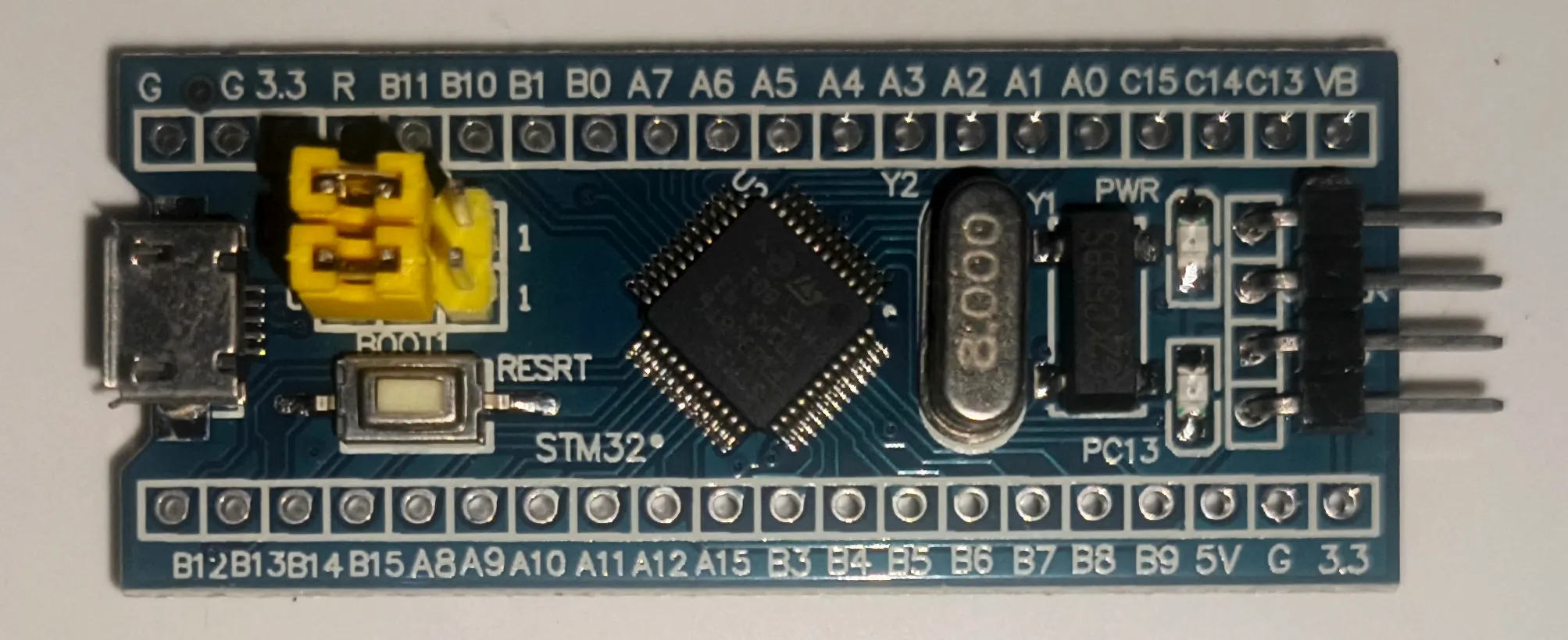
System minimum board STM32F103C8T6 (Blue Pill) ST-Link USB Debugger & Programmer
The ST-Link USB Debugger & Programmer serves as the interface between your PC/laptop and the STM32F103C8, allowing us to flash and debug programs directly from our computer.

ST-Link USB Downloader Debuger for Programming the Blue Pill board Breadboard
A breadboard (also known as a project board) is used to create electronic circuit prototypes without the need for soldering.

Breadboard (Project Board) Push Button
The push button will be used as an input to the STM32F103C8 GPIO pin. The two pins of the push button are connected when the button is pressed, allowing electrical current to flow between them.

Push Button Jumper Wires (Male-to-Male and Female-to-Female)
Female-to-female jumper wires are used to connect the Blue Pill to the ST-Link USB Debugger. Meanwhile, male-to-male jumper wires are used to build the circuits on the breadboard.
Using External Interrupts on the STM32F103C8 (Blue Pill) with Rust
In this tutorial, we will demonstrate how to use external interrupt 0 on the Blue Pill to detect a falling edge on GPIO pin PA0.
Circuit Schematic for External Interrupts
First, prepare all the necessary components, then build the circuit on the breadboard according to the following schematic diagram:
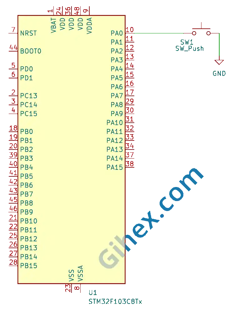
As shown in the diagram, when the push button is pressed, pin PA0 will be connected to GND (0V). We will configure pin PA0 as an input pull-up, so its default state will be HIGH. When the button is pressed, a voltage transition from 3.3V to 0V will occur on pin PA0 (triggering a falling edge).
Creating an External Interrupt Program on the STM32F103C8 (Blue Pill) Using Rust
First, we will create a Rust project for embedded systems as explained in this article. Open the Cargo.toml file and add the following code to define a new binary executable named gpio-external-interrupt :
Toml
1[[bin]]
2name = "gpio-external-interrupt"
3path = "src/main.rs"
4test = false
5bench = falseCargo.toml 🔒The Gihex website relies on revenue from Smartlink/Directlink advertisements for its operational costs. To display the complete code for “Cargo.toml”, simply click the following Smartlink/Directlink button:
Next, open the src/main.rs file and insert the following code:
Rust
 1#![no_std]
 2#![no_main]
 3
 4use defmt_rtt as _;
 5use panic_probe as _;
 6
 7use cortex_m_rt::entry;
 8use stm32f1xx_hal::{
 9    flash::FlashExt,
10    gpio::ExtiPin,
11    pac::{self, interrupt},
12    prelude::*,
13    rcc::{Config, RccExt},
14    time::Hertz,
15    timer::Timer,
16};
Configure the Rust toolchain to avoid using the standard library, ensuring the program runs on bare-metal without an operating system.
Defining the libraries (crates) to be used:
cortex_m_rtcrate: Used to define the entry point of the program and handle the startup process.defmt_rtt: Functions to transmit logging data to a PC/laptop using the Real-Time Transfer (RTT) protocol.stm32f1xx_halcrate: Provides safe access to the STM32F103C8 microcontroller peripherals.panic_probe: Used to handle runtime errors by automatically sending error logs to the host PC/laptop.
Inside the main function, insert the following code:"
Rust
1defmt::println!("STM32F103C8 External interrupt");Send a message to the PC/laptop terminal to identify the program as an external interrupt program.
Rust
1let dp = pac::Peripherals::take().unwrap();
2
3let cp = cortex_m::Peripherals::take().unwrap();
Accessing the STM32F103C8 peripherals and the Cortex-M3 CPU peripherals.
Rust
 1let mut flash = dp.FLASH.constrain();
 2
 3let rcc = dp.RCC.constrain();
 4
 5let clock_config = Config::default()
 6    .use_hse(Hertz::MHz(8))
 7    .sysclk(Hertz::MHz(72))
 8    .hclk(Hertz::MHz(72));
 9
10let mut clocks = rcc.freeze(clock_config, &mut flash.acr);
Configure the clock by using an 8 MHz external clock ( use_hse ), then set the system clock ( sysclk ) to 72 MHz and the Advanced High-Performance Bus clock ( hclk ) to 72 MHz.
Rust
1let mut gpioa = dp.GPIOA.split(&mut clocks);
2
3let mut pa0 = gpioa.pa0.into_pull_up_input(&mut gpioa.crl);
Accessing the GPIO Port A peripherals and configuring pin PA0 as a pull-up input.
Rust
1let mut afio = dp.AFIO.constrain(&mut clocks);
2let mut exti = dp.EXTI;
Accessing the AFIO (Alternate Function Input/Output) and EXTI (External Interrupt) peripherals.
Rust
1pa0.make_interrupt_source(&mut afio);Using pin PA0 as the external interrupt source.
Rust
1// trigger on falling edge
2pa0.trigger_on_edge(&mut exti, stm32f1xx_hal::gpio::Edge::Falling);
Configure pin PA0 to detect a falling edge. Here, we specify the type of edge to be detected (rising edge, falling edge, or both rising and falling edges).
Rust
1// enable interrupt
2pa0.enable_interrupt(&mut exti);
Enabling the external interrupt on pin PA0.
Rust
1unsafe {
2    pac::NVIC::unmask(pac::interrupt::EXTI0);
3}
Enabling the EXTI0 interrupt in the NVIC (Nested Vectored Interrupt Controller).
Rust
1let mut delay = Timer::syst_external(cp.SYST, &mut clocks.clocks).delay();Creating a delay using the System Timer ( SysTick ).
Rust
1loop {
2    defmt::println!("Main program");
3    delay.delay_ms(1000u32);
4}
Creating the main loop to continuously send a message to the PC/laptop terminal every 1 second.
Rust
1#[interrupt]
2fn EXTI0() {
3    let exti = unsafe { &*pac::EXTI::ptr() };
4
5    // clear pending register bit 0 (EXTI0)
6    exti.pr().write(|w| w.pr0().bit(true));
7
8    defmt::println!("interrupt: push button pressed");
9}
Creating an Interrupt Service Routine (ISR) that executes when an external interrupt occurs on EXTI0 . This function will clear pending register bit 0 ( EXTI0 ) and send a message to the PC/laptop terminal when a falling edge is detected on pin PA0 due to a button press.
src/main.rs 🔒The Gihex website relies on revenue from Smartlink/Directlink advertisements for its operational costs. To display the complete code for “src/main.rs”, simply click the following Smartlink/Directlink button:
Run the program by executing the command ‘cargo run --bin gpio-external-interrupt’ in the terminal within the project folder.
Source Code
The source code used in this article can be accessed at the 🔒GitHub repository .
If you encounter any issues following this tutorial, feel free to reach out to us through the contact page.