Mastering GPIO on STM32 Blue Pill: The Modern Way with Rust
Before you begin, make sure to check out our previous guide: Setup STM32F103C8 with Rust. This tutorial uses the same hardware and project structure. For better clarity, we have included line-by-line comments explaining each function within the Rust code.
The STM32F103C8 is equipped with GPIO (General Purpose Input Output) peripherals that can be programmed to suit our needs. Each GPIO pin can be configured as an input, an output, or an alternate peripheral function. In this tutorial, we will focus on programming the STM32F103C8 GPIO as input and output. Alternate peripheral functions (such as PWM, UART, SPI, etc.) will be discussed in detail in our upcoming articles.
Hardware Preparation
In addition to the hardware mentioned in the previous article, we will also use several additional components such as a breadboard, push buttons, and some male-to-male jumper wires to build the circuit on the breadboard.
Breadboard
A Breadboard (also known as a Project Board) is a board used for creating electronic circuit prototypes. By using a breadboard, circuit prototypes can be built faster and more neatly without the need for soldering.

Push Button
The push button will be used as an input to the STM32F103C8 GPIO pin. When pressed, the two terminals of the push button will connect, allowing electric current to flow between them.

Programming STM32F103C8 GPIO as Output with Rust
A GPIO pin configured as an output serves as a pathway for electrical signals to leave the microcontroller, allowing it to control other devices (such as relays, transistors, small LEDs, etc.). On the STM32F103C8, the output pin voltage is 3.3V, with a recommended current of 8 mA per pin, except for pins PC13, PC14, and PC15, which can only supply up to 3 mA. Therefore, if we want to control devices with higher current or voltage requirements, we must use additional components like relays or transistors.
Configuring STM32F103C8 GPIO Pins as Output
When used as an output, the STM32F103C8 GPIO pins can be configured into two modes:
- Push-Pull Output: When the pin is set to logic HIGH, it connects to VCC, allowing it to provide electrical current (Source). Conversely, when set to logic LOW, the pin connects to GND, drawing electrical current into it (Sink).
- Open-Drain Output: When the pin is set to logic HIGH, it is not connected to either VCC or GND (floating). When set to logic LOW, the pin connects to GND and will draw electrical current into it (Sink).
Programming STM32F103C8 GPIO Pins as Output
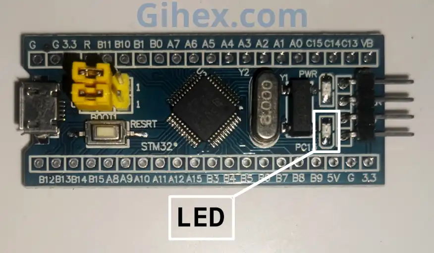
In this tutorial, we will practice controlling the on-board (built-in) LED on the STM32F103C8 Blue Pill board. The built-in LED on the Blue Pill is connected to pin PC13 and is active-low, meaning the LED will turn ON when the pin is set to logic LOW.
First, we will create a new Rust project as described in the previous article. In that project, open the src/main.rs file and replace its content with the following code:
 1#![no_std]
 2#![no_main]
 3
 4use defmt_rtt as _;
 5use panic_probe as _;
 6
 7use cortex_m::delay::Delay;
 8use cortex_m_rt::entry;
 9use stm32f1xx_hal::{
10    flash::FlashExt,
11    gpio::GpioExt,
12    pac,
13    rcc::{Config, RccExt},
14    time::Hertz,
15};
16
17#[entry]
18fn main() -> ! {
19    defmt::println!("STM32F103C8 GPIO as Output");
20
21    // Access the STM32F103C8 device peripherals
22    let dp = pac::Peripherals::take().unwrap();
23
24    // Access the STM32F103C8 core peripherals (Cortex-M3)
25    let cp = pac::CorePeripherals::take().unwrap();
26
27    // Access the FLASH peripheral to adjust memory 'wait states'
28    // during clock configuration.
29    let mut flash = dp.FLASH.constrain();
30
31    // Access the Reset & Clock Control (RCC) peripheral
32    // for configuration
33    let rcc = dp.RCC.constrain();
34
35    // Create the Reset & Clock Control (RCC) configuration
36    let clock_config = Config::default()
37        // Use an external 8MHz crystal (HSE)
38        .use_hse(Hertz::MHz(8))
39        // Set the CPU frequency to 72MHz
40        .sysclk(Hertz::MHz(72))
41       // Set the BUS frequency (SRAM and FLASH access path) to 72MHz
42        .hclk(Hertz::MHz(72));
43
44    // Apply the clock configuration to the RCC and
45    // adjust the flash memory wait states
46    let mut clocks = rcc.freeze(clock_config, &mut flash.acr);
47
48    // Create a delay instance using the System Timer (SysTick)
49    let mut delay = Delay::new(cp.SYST, clocks.clocks.hclk().to_Hz());
50
51    // Access the GPIO Port C peripheral
52    let mut gpioc = dp.GPIOC.split(&mut clocks);
53
54    // Configure GPIOC pin 13 (PC13) as an open-drain output to
55    // control the LED. (crl: pins 0-7; crh: pins 8-15)
56    let mut led = gpioc.pc13.into_open_drain_output(&mut gpioc.crh);
57
58    // Wait for 5 seconds and observe the initial LED state
59    defmt::println!("Default logic value of pin output:");
60    defmt::println!("\tlow: {}", led.is_set_low());
61    defmt::println!("\thigh: {}", led.is_set_high());
62    delay.delay_ms(5000);
63
64    // The program will now run in a continuous loop
65    loop {
66        // Send status message to PC/laptop
67        defmt::println!("LED off");
68        // Set the LED pin (PC13) to logic HIGH
69        led.set_high();
70        // Delay for 2 seconds
71        delay.delay_ms(2000);
72
73        //Send status message to PC/laptop
74        defmt::println!("LED on");
75        // Set the LED pin (PC13) to logic LOW
76        led.set_low();
77        // Delay for 2 seconds
78        delay.delay_ms(2000);
79    }
80}
Run the program by typing the ‘cargo run --bin gpio-output’ command in the VS Code terminal. The following is the output of the program we have created:
When pin PC13 is set to HIGH, the pin becomes floating (not connected to either VCC or GND), which prevents current from flowing and keeps the LED OFF. Conversely, when PC13 is set to LOW, the pin connects to GND, allowing current to flow to Ground and turning the LED ON.
Pro Tip: To stop the debugging process in the PC/laptop terminal, you can press the CTRL+C keys on your keyboard simultaneously.
From the results, we can also see that by default, the output pin starts with a LOW logic state. Consequently, the LED will turn ON as soon as the microcontroller is powered up. This behavior can be very dangerous if we are controlling active-low devices, as they will trigger immediately upon startup. To resolve this issue, we can replace the code on line 56 with the following:
1let mut led = gpioc
2        .pc13
3        // pin as output open-drain with initial state HIGH
4        .into_open_drain_output_with_state(&mut gpioc.crh, PinState::High);
By using this code, the PC13 pin will immediately be set to HIGH when configured as an output, ensuring the LED does not turn ON at startup.
Actually, we can also use the push-pull output mode by replacing the code on line 56 with the following:
1let mut led = gpioc
2        .pc13
3        // pin as output push-pull with initial state HIGH
4        .into_push_pull_output_with_state(&mut gpioc.crh, PinState::High);
When pin PC13 is set to HIGH, it connects to VCC. This results in no potential difference between the LED’s anode and cathode, meaning no electric current flows and the LED remains OFF. Conversely, when pin PC13 is set to LOW, the pin connects to GND, creating a current flow to Ground and turning the LED ON.
Warning: When using push-pull mode to control a device that operates on a supply voltage higher than 3.3V (VCC > 3.3V), a potential difference will persist. As a result, the device may remain ON even when the pin is set to HIGH.
Programming STM32F103C8 GPIO as Input with Rust
A GPIO pin configured as an input serves to read voltage levels from external devices. The standard voltage tolerance for STM32F103C8 pins is a maximum of 3.6V. However, several specific pins are 5V-tolerant; for more detailed information, please refer to the STM32F103C8 datasheet.
Configuring STM32F103C8 GPIO Pins as Input
When used as an input, the STM32F103C8 GPIO pins can be configured into four modes:
- Floating Input: The pin is not connected to any internal pull-up or pull-down resistors. To use this mode, the external device must provide its own voltage conditioning to the pin; otherwise, the input value will be noisy (constantly fluctuating).
- Input Pull-Up: The pin is connected to an internal pull-up resistor (connected to VCC), making its default state HIGH. To change the state, the pin must be connected to GND.
- Input Pull-Down: The pin is connected to an internal pull-down resistor (connected to GND), making its default state LOW. To change the state, the pin must be supplied with 3.3V (or 5V if the pin is 5V-tolerant).
- Analog Input: The pin is connected to the ADC (Analog-to-Digital Converter) peripheral to read the digital value of the applied voltage. The STM32F103C8 ADC has a 12-bit resolution (0-4095): an input voltage of 0V produces a digital value of 0, while an input voltage of 3.3V produces a digital value of 4095.
Warning: When a 5V-tolerant GPIO pin on the STM32F103C8 is switched to Analog Input mode, it can only accept a maximum voltage of 3.3V. Applying 5V in this mode may potentially damage the pin and will result in inaccurate ADC readings.
Configuring STM32F103C8 GPIO Pins as Input Pull-Up
We will use a push button as an input for the STM32F103C8 GPIO pin PB0. First, let’s assemble the STM32F103C8 and the push button on a breadboard according to the following schematic diagram:
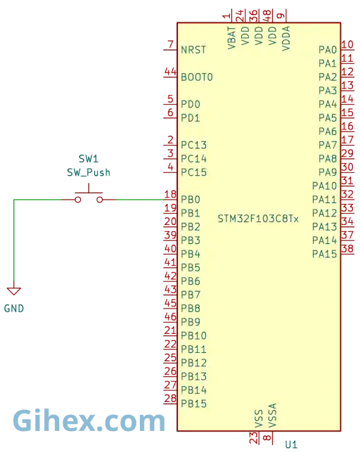
In this circuit, when the push button is pressed, pin PB0 will be connected to GND, resulting in a LOW state. Therefore, in our program, we will configure pin PB0 as an Input Pull-Up to detect the change when the push button is pressed.
Next, in the Rust project we just created, open the Cargo.toml file and add the following code to define a new binary output:
1[[bin]]
2name = "gpio-input-pullup"
3path = "src/input_pullup.rs"
4test = false
5bench = false
Pro Tip: By adding a
[[bin]]section, we can have multiple executable files within the same Cargo project. This is very useful for organizing different experiments or tutorials, such as having one file for ‘LED Blink’ and another for ‘Push Button Input’, without creating separate projects.
Create a file named src/input_pullup.rs and fill it with the following code:
 1#![no_std]
 2#![no_main]
 3
 4use defmt_rtt as _;
 5use panic_probe as _;
 6
 7use cortex_m::delay::Delay;
 8use cortex_m_rt::entry;
 9use stm32f1xx_hal::{
10    flash::FlashExt,
11    gpio::GpioExt,
12    pac,
13    rcc::{Config, RccExt},
14    time::Hertz,
15};
16
17#[entry]
18fn main() -> ! {
19    defmt::println!("STM32F103C8 Access GPIO as Input Pull Up");
20
21    // Access STM32F103C8 device peripherals
22    let dp = pac::Peripherals::take().unwrap();
23
24    // Access STM32F103C8 core peripherals (Cortex-M3)
25    let cp = pac::CorePeripherals::take().unwrap();
26
27    // Access the FLASH peripheral to adjust memory 'wait states'
28    // during clock configuration.
29    let mut flash = dp.FLASH.constrain();
30
31    // Access the Reset & Control Clock (RCC) peripheral for configuration
32    let rcc = dp.RCC.constrain();
33
34    // Create the Reset & Control Clock (RCC) configuration
35    let clock_config = Config::default()
36        // Use an external 8MHz crystal (HSE)
37        .use_hse(Hertz::MHz(8))
38        // Set CPU frequency to 72MHz
39        .sysclk(Hertz::MHz(72))
40        // Set BUS frequency (SRAM and FLASH access path) to 72MHz
41        .hclk(Hertz::MHz(72));
42
43    // Apply the clock configuration to the RCC and
44    // adjust flash memory wait states
45    let mut clocks = rcc.freeze(clock_config, &mut flash.acr);
46
47    // Create a delay instance using the System Timer (SysTick)
48    let mut delay = Delay::new(cp.SYST, clocks.clocks.hclk().to_Hz());
49
50    // Access the GPIO Port B peripheral
51    let mut gpiob = dp.GPIOB.split(&mut clocks);
52
53    // Configure pin PB0 as an input pull-up
54    let button_pullup = gpiob.pb0.into_pull_up_input(&mut gpiob.crl);
55
56    // Wait for 50ms (initial stabilization)
57    delay.delay_ms(50);
58
59    loop {
60        // Check if the button is pressed; if so, PB0 will be LOW
61        if button_pullup.is_low() {
62            // Send message to PC/laptop
63            defmt::println!("button_pullup is pressed");
64            // Delay for 500ms to avoid multiple triggers (simple debouncing)
65            delay.delay_ms(500);
66        }
67    }
68}
Run the program by typing the ‘cargo run --bin gpio-input-pullup’ command in the VSCode terminal and try pressing the push button. The following is the output of the program we have created:
Programming STM32F103C8 GPIO Pins as Input Pull-Down
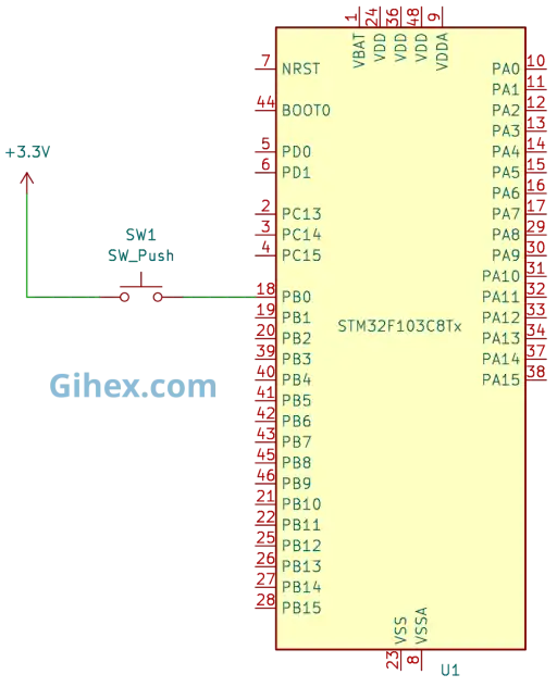
We can also use pin PB0 as an Input Pull-Down, however push button circuit must be modified. Instead of connecting it to GND, it should now be connected to VCC or 3.3V, as shown in the following schematic diagram:
Open Cargo.toml file then add the following code:
1[[bin]]
2name = "gpio-input-pulldown"
3path = "src/input_pulldown.rs"
4test = false
5bench = false
When the push button is pressed, pin PB0 will read as HIGH; conversely, when it is not pressed, it will read as LOW. Please create a file named src/input_pulldown.rs and fill it with the following code:
 1#![no_std]
 2#![no_main]
 3
 4use defmt_rtt as _;
 5use panic_probe as _;
 6
 7use cortex_m::delay::Delay;
 8use cortex_m_rt::entry;
 9use stm32f1xx_hal::{
10    flash::FlashExt,
11    gpio::GpioExt,
12    pac,
13    rcc::{Config, RccExt},
14    time::Hertz,
15};
16
17#[entry]
18fn main() -> ! {
19    defmt::println!("STM32F103C8 Access GPIO as Input Pull Down");
20
21    // Access STM32F103C8 device peripherals
22    let dp = pac::Peripherals::take().unwrap();
23
24    // Access STM32F103C8 core peripherals (Cortex-M3)
25    let cp = pac::CorePeripherals::take().unwrap();
26
27    // Access the FLASH peripheral to adjust 'wait states'
28    // during clock configuration.
29    let mut flash = dp.FLASH.constrain();
30
31    // Access the Reset & Control Clock (RCC) peripheral for configuration
32    let rcc = dp.RCC.constrain();
33
34    // Create the Reset & Control Clock (RCC) configuration
35    let clock_config = Config::default()
36        // Use an external 8MHz crystal (HSE)
37        .use_hse(Hertz::MHz(8))
38        // Set CPU frequency to 72MHz
39        .sysclk(Hertz::MHz(72))
40        // Set BUS frequency (SRAM and FLASH access path) to 72MHz
41        .hclk(Hertz::MHz(72));
42
43    // Apply the clock configuration to the RCC and
44    // adjust flash memory wait states
45    let mut clocks = rcc.freeze(clock_config, &mut flash.acr);
46
47    // Create a delay instance using the System Timer (SysTick)
48    let mut delay = Delay::new(cp.SYST, clocks.clocks.hclk().to_Hz());
49
50    // Access the GPIO Port B peripheral
51    let mut gpiob = dp.GPIOB.split(&mut clocks);
52
53    // Configure pin PB0 as an input pull-down
54    let button_pulldown = gpiob.pb0.into_pull_down_input(&mut gpiob.crl);
55
56    // Wait for 50ms (initial stabilization)
57    delay.delay_ms(50);
58
59    loop {
60        // Check if the button is pressed; PB0 will be HIGH in this state
61        if button_pulldown.is_high() {
62            // Send message to PC/laptop
63            defmt::println!("button_pulldown is pressed");
64            // Delay for 500ms (simple debouncing)
65            delay.delay_ms(500);
66        }
67    }
68}
Please try running the program using the ‘cargo run --bin gpio-input-pulldown’ command, then press the push button and observe the results for yourself.
Common Issues and Solutions
The following are the issues encountered during the creation of this tutorial:
- Ghost Triggering: When configuring the STM32F103C8 GPIO pins as an input pull-up, the push button sometimes acts as if it is being pressed when the program first starts, even though no one has touched it. To resolve this issue, add a delay of approximately 50ms after configuring the pins or before entering the main loop.
If you encounter any other issues or have any questions, critiques, or suggestions, please feel free to reach out to us via our contact page.
For your convenience, the source code used in this tutorial is available on our Github repository.