Measuring Pulse Width with STM32 Timer Input Capture using Rust
In the previous article, we discussed the STM32F103C8 Timer and how to use it as a counter. This time, we will explore using the STM32F103C8 Timer channels for input capture. Input capture is commonly used for reading RPM on a tachometer, decoding remote control signals, measuring input pulse widths, and more.
What is Input Capture?
Input capture is a feature of the STM32F103C8 Timer used to store the timer’s counter value when a voltage transition occurs on an input pin (Timer channel). When a voltage change is detected on the Timer channel, the system automatically copies the value from the counter register (TIMx_CNT) into the TIMx_CCR (Capture/Compare Register). The following are the types of voltage transitions that the input capture feature can detect:
- Rising edge: The input capture only copies the
TIMx_CNTregister value to theTIMx_CCRregister when a voltage transition from 0V to 3.3V (LOW to HIGH) occurs. - Falling edge: The input capture only copies the
TIMx_CNTregister value to theTIMx_CCRregister when a voltage transition from 3.3V to 0V (HIGH to LOW) occurs. - Both edges (Rising/Falling edge): The input capture copies the
TIMx_CNTregister value to theTIMx_CCRregister during any voltage transition, whether from 0V to 3.3V (LOW to HIGH) or 3.3V to 0V (HIGH to LOW).
By using the difference between the TIMx_CCR register values when voltage transitions occur, we can determine the duration from the first transition to the second (the pulse width). The following is the equation used to find the duration (pulse width) between two events on a Timer channel:
Key:
- : The period between two events on the Timer channel (pulse width).
-
: The difference between
TIMx_CCRregister values when voltage transitions occur. - : The frequency of the Timer being used.
-
: The value of the Capture/Compare Register (
TIMx_CCR).
Hardware Preparation
The components used in this tutorial include: an STM32F103C8 microcontroller (Blue Pill), an ST-Link USB Downloader/Debugger, a breadboard, a push button, and several jumper wires (both female-to-female and male-to-male).
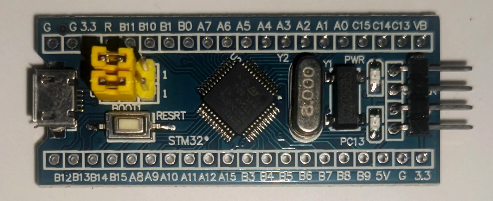
Microntroller STM32F103C8 (Blue Pill):
This is the primary component required. We will be accessing the Timer peripherals of the STM32F103C8 microcontroller.
Blue Pill minimum system board ST-Link USB Downloader/Debugger:
The ST-LINK USB Downloader/Debugger is used to program and debug the STM32F103C8 microcontroller. This component bridges the connection between your PC/laptop and the STM32F103C8.
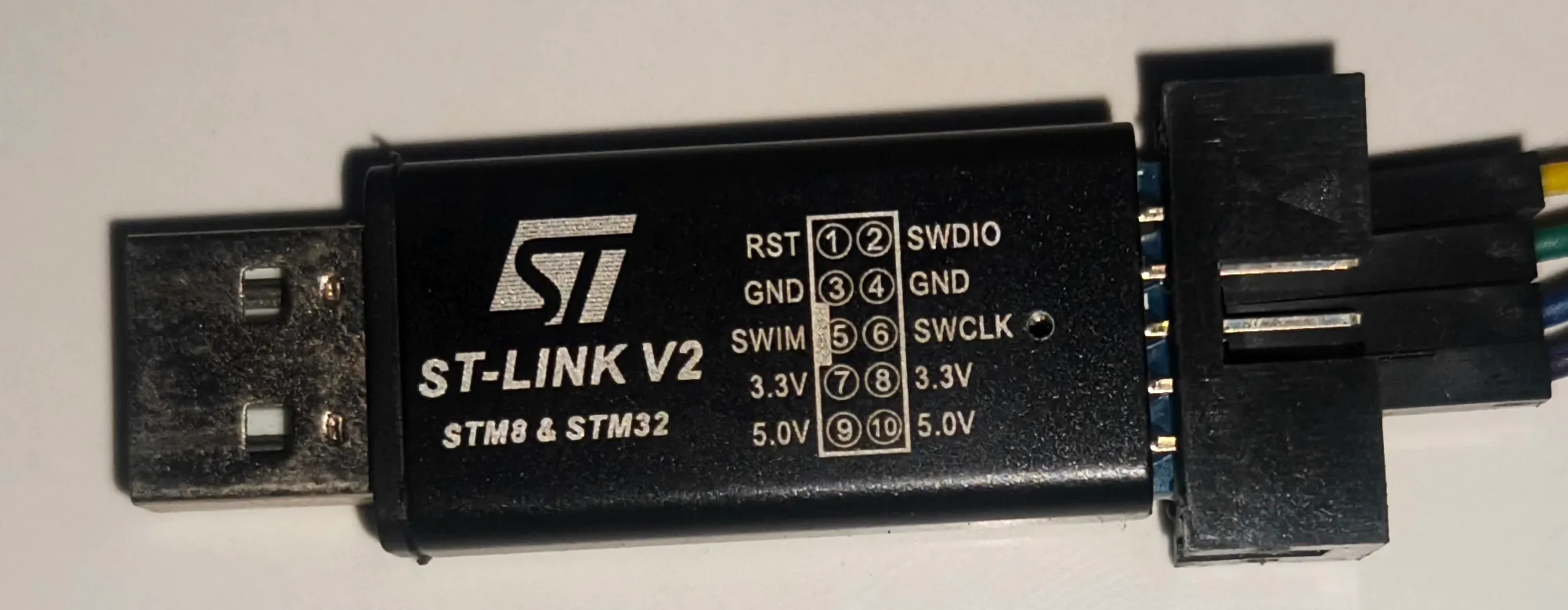
ST-Link USB Downloader/Debugger for programming the STM32F103C8 Breadboard:
A breadboard is used for prototyping electronic circuits. By using a breadboard, we can avoid soldering components and simply use male-to-male jumper wires instead.
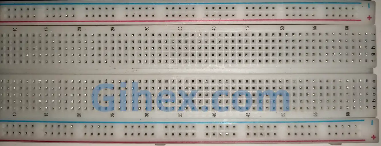
Breadboard for easy electronic circuit prototyping Push button:
The push button serves as the input for the STM32F103C8 Timer channel. When the button is pressed, its two terminals become connected.
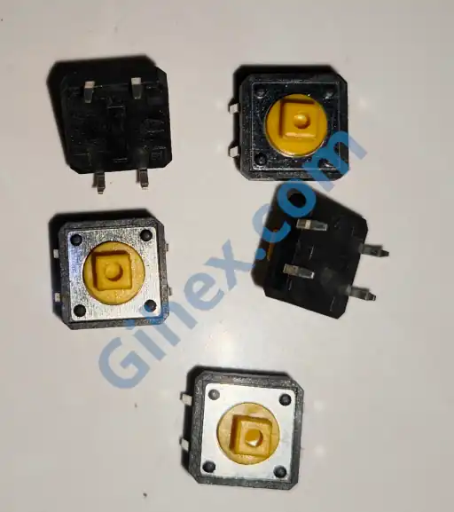
Push button as an input to the STM32F103C8 Jumper wires:
Jumper wires are used to connect components on the breadboard and to link the Blue Pill to the ST-Link USB Downloader/Debugger.
More detailed explanations regarding the functions of the components used can be found on the Setting up STM32F103C8 with Rust page and the Using STM32F103C8 GPIO with Rust page.
STM32F103C8 Timer as Input Capture with Rust
In this article, we will use the timer for input capture in a simple application: measuring how long a push button is pressed. Although basic, this is the foundational concept used for reading sensors such as tachometers, ultrasonic distance sensors (HC-SR04), and more.
We will utilize Timer 2 Channel 1 (pin PA0) as the input capture. A push button will provide the input pulses to Timer 2 Channel 1. When the button is pressed, a voltage transition occurs on pin PA0. This voltage transition is what the input capture feature will detect.
In this tutorial, we will configure Timer 2 Channel 1 to toggle between rising edge and falling edge modes alternately, as Timer 2 does not natively support both edges mode.
STM32F103C8 Schematic Circuit for Input Capture
One pin of the push button is connected to Timer 2 Channel 1 (pin PA0) of the STM32F103C8 microcontroller, while the other pin is connected to the 3.3V supply. We will also configure pin PA0 (Timer 2 Channel 1) as an input pull-down. Below is the circuit schematic used, please assemble the circuit on your breadboard:
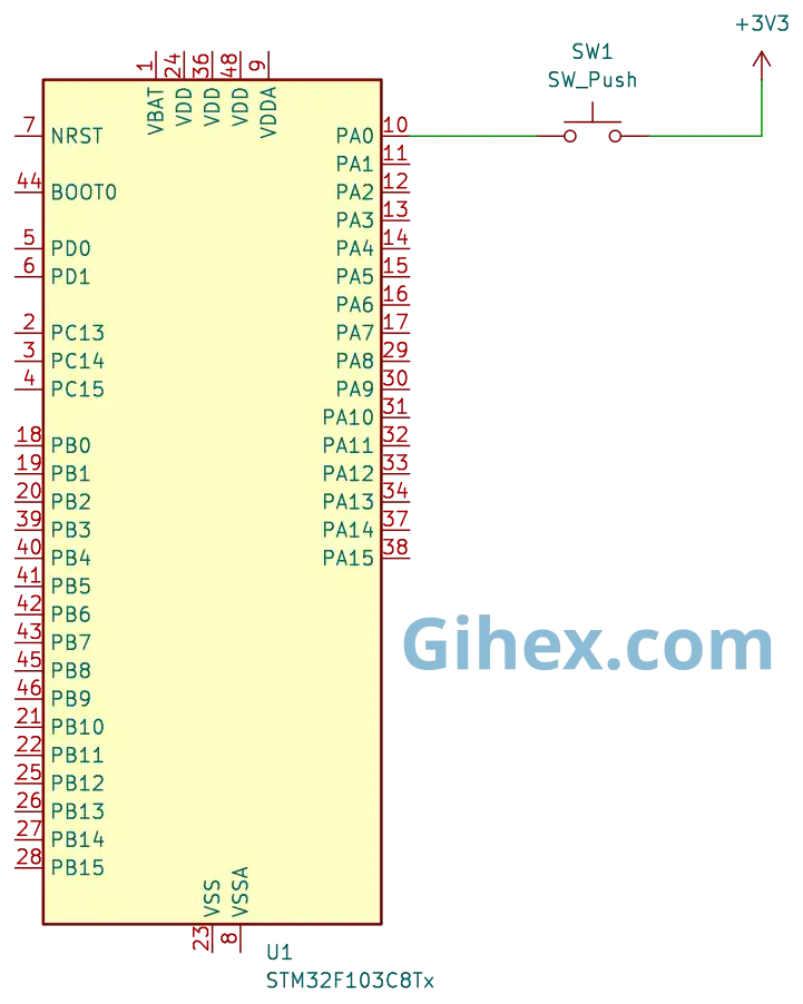
Timer 2 (TIM2) channel 1When the push button is pressed, pin PA0 (Timer 2 Channel 1) connects to the 3.3V supply, triggering the input capture to detect a voltage transition (Rising edge). Since pin PA0 is configured as an input pull-down, once the button is released, the pin pulls back to GND, allowing the input capture to detect the return transition (Falling edge). By calculating the difference between the TIMx_CCR register values at the Rising edge and the Falling edge, we can determine exactly how long the push button was held down.
Programming STM32F103C8 Timer as Input Capture with Rust
First, let’s create a new Rust project as described on this page. Open your Cargo.toml file and add the following code to define a new executable binary named timer-input-capture :
1[[bin]]
2name = "timer-input-capture"
3path = "src/main.rs"
4test = false
5bench = false
Next, open the src/main.rs file and add the following code to inform the compiler that this program will not use the standard library:
 1#![no_std]
 2#![no_main]
 3
 4use defmt_rtt as _;
 5use panic_probe as _;
 6
 7use cortex_m_rt::entry;
 8use stm32f1xx_hal::{
 9    flash::FlashExt,
10    pac,
11    prelude::*,
12    rcc::{Config, RccExt},
13    time::Hertz,
14    timer::Timer,
15};
Informs the compiler not to use the standard library and indicates that the program is not running on an operating system.
The cortex_m_rt library/crate is used to define the program’s entry point and handle the startup process. defmt_rtt is used to send data to a PC/laptop for logging via the Real-Time Transfer (RTT) protocol. The stm32f1xx_hal library allows for safe access to the STM32F103C8 microcontroller peripherals. Finally, panic_probe is used to handle runtime errors by automatically transmitting error logs to the host PC/laptop.
1defmt::println!("STM32F103C8 Timer as Input Capture");Sends a message to the PC/laptop to signify that the input capture program is running.
 1let dp = pac::Peripherals::take().unwrap();
 2
 3let mut flash = dp.FLASH.constrain();
 4
 5let rcc = dp.RCC.constrain();
 6
 7let clock_config = Config::default()
 8    .use_hse(Hertz::MHz(8))
 9    .sysclk(Hertz::MHz(72))
10    .hclk(Hertz::MHz(72))
11    .pclk1(Hertz::MHz(36));
12
13let mut clocks = rcc.freeze(clock_config, &mut flash.acr);
Accessing the Flash and RCC (Reset Clock & Control) peripherals. Then, configuring the system using an 8 MHz external clock (HSE) to set the system clock to 72 MHz, the Advanced High-performance Bus (AHB) clock to 72 MHz, and the Peripheral Clock 1 (APB1) to 36 MHz. Consequently, the clock prescaler for Peripheral 1 is set to 2.
As explained in the previous article, when the Peripheral 1 clock prescaler is greater than 1, the clock frequency for General Purpose Timers becomes twice the Peripheral 1 clock frequency. Therefore, the General Purpose Timer clock frequency will be
1let mut gpioa = dp.GPIOA.split(&mut clocks);
2
3let channel_1 = gpioa.pa0.into_pull_down_input(&mut gpioa.crl);
Accessing the GPIO peripherals and configuring pin PA0 (Timer 2 Channel 1) as an input with an internal pull-down configuration.
1let timer2 = Timer::new(dp.TIM2, &mut clocks);
2
3let mut counter = timer2.counter_hz();
Utilizing the Timer 2 peripheral. Using the counter_hz method to enable the Timer 2 counter.
1let timer_register = unsafe { &*pac::TIM2::ptr() };Accessing the Timer 2 register pointer directly.
1timer_register.ccmr1_input().modify(|_, w| w.cc1s().ti1());Enabling Channel 1 (pin PA0) as the input for Timer 2 (without pin remapping).
1timer_register
2    .ccmr1_input()
3    .modify(|_, w| w.ic1f().fck_int_n8());
Enabling the digital filter on Timer 2 Channel 1 to reduce debounce and noise.
1timer_register.ccer().modify(|_, w| w.cc1e().set_bit());Enabling input capture on Timer 2 Channel 1.
1timer_register.ccer().modify(|_, w| w.cc1p().clear_bit());Configuring Timer 2 Channel 1 to detect the rising edge.
Note: When the
CCxPbit is set to 0, the channel will detect the Rising Edge. Conversely, when it is set to 1, it will detect the Falling Edge.
1// set frquency timer to 10KHz dan Arr to max
2counter.start_raw(7199, 65535);
Starting the counter with a timer prescaler configuration (TIMX_PSC) of 7199 and setting the Auto-Reload Register (TIMX_ARR) to its maximum value of 65535.
Unlike the previous article, where we defined the timer frequency directly and let the stm32f10xx_hal calculate the prescaler, in this tutorial, we are manually defining the prescaler and setting the auto-reload register to its maximum value. This allows us to measure longer durations of time.
By using a prescaler of 7199, the timer frequency becomes 10 kHz (10, 000 Hz). This means the timer can detect transitions with a precision of . The calculation for the timer frequency is as follows:
1let mut start_press_tick = 0u16;
2
3let mut is_pressed = false;
Creating a variable to store the tick value when the push button is start pressed, and a variable to track the status of whether the push button is currently pressed or not.
1loop {
2    if timer_register.sr().read().cc1if().bit_is_set() {
3
4    }
5}
Inside the loop block, we monitor for voltage changes on pin PA0 (Timer 2 Channel 1). When the CCxP bit is set to 0 (detecting a rising edge), the CC1IF (Interrupt Flag) bit will be set to 1 if the voltage transitions from GND to 3.3V (LOW to HIGH). Conversely, if the CCxP bit is set to 1 (detecting a falling edge), the CC1IF bit will become 1 if the voltage transitions from 3.3V to GND (HIGH to LOW). During these transitions, the value of the TIMx_CNT register is automatically copied (captured) into the TIMx_CCR register.
 1let captured_tick = timer_register.ccr1().read().ccr().bits();
 2
 3let pin_is_high = channel_1.is_high();
 4
 5if pin_is_high && !is_pressed {
 6    // Push button start pressed
 7    start_press_tick = captured_tick;
 8    timer_register.ccer().modify(|_, w| w.cc1p().set_bit());
 9
10    is_pressed = true;
11    defmt::println!("--- Button Pressed ---");
12    defmt::println!("start: {}", start_press_tick);
13} else if !pin_is_high && is_pressed {
14    // Push button end pressed
15    let delta = captured_tick.wrapping_sub(start_press_tick);
16    timer_register.ccer().modify(|_, w| w.cc1p().clear_bit());
17
18    defmt::println!("end: {} | delta: {}", captured_tick, delta);
19    defmt::println!("press long: {} ms", delta as f32 / 10f32);
20    defmt::println!("----------------------");
21    is_pressed = false;
22}
23
24timer_register.sr().modify(|_, w| w.cc1if().clear_bit());
If a voltage change occurs on pin PA0 (Timer 2 Channel 1), retrieve the value from the TIMx_CCR register and check the status of pin PA0. If the pin status is HIGH and is_pressed is false, it indicates that the push button has just been pressed. Conversely, if these conditions are not met, the push button has been released.
When the push button is initially pressed (rising edge), update the start_press_tick variable with the current TIMx_CCR register value, then switch the input capture detection mode to falling edge by setting the CCxP bit to 1. Additionally, update the is_pressed status to true.
When the push button is released (falling edge), calculate the difference between the TIMx_CCR values at the rising edge and falling edge using the wrapping_sub method. Then, reset the input capture mode back to rising edge by clearing the CCxP bit (setting it to 0). Calculate the duration of the button press according to the formula above and set the is_pressed variable to false.
Finally, do not forget to reset the CCxIF register bit. While this register is technically reset automatically when the TIMx_CCR value is read, we perform a manual reset to ensure absolute certainty.
Calculating the button press duration:
 1#![no_std]
 2#![no_main]
 3
 4use defmt_rtt as _;
 5use panic_probe as _;
 6
 7use cortex_m_rt::entry;
 8use stm32f1xx_hal::{
 9    flash::FlashExt,
10    pac,
11    prelude::*,
12    rcc::{Config, RccExt},
13    time::Hertz,
14    timer::Timer,
15};
16
17#[entry]
18fn main() -> ! {
19    defmt::println!("STM32F103C8 Timer as Input Capture");
20
21    let dp = pac::Peripherals::take().unwrap();
22
23    let mut flash = dp.FLASH.constrain();
24
25    let rcc = dp.RCC.constrain();
26
27    let clock_config = Config::default()
28        .use_hse(Hertz::MHz(8))
29        .sysclk(Hertz::MHz(72))
30        .hclk(Hertz::MHz(72))
31        .pclk1(Hertz::MHz(36));
32
33    let mut clocks = rcc.freeze(clock_config, &mut flash.acr);
34
35    let mut gpioa = dp.GPIOA.split(&mut clocks);
36
37    let channel_1 = gpioa.pa0.into_pull_down_input(&mut gpioa.crl);
38
39    let timer2 = Timer::new(dp.TIM2, &mut clocks);
40
41    let mut counter = timer2.counter_hz();
42
43    let timer_register = unsafe { &*pac::TIM2::ptr() };
44
45    // 00 output
46    // 01 input
47    // 10 Input, (Cross-mapping channel 2).
48    timer_register.ccmr1_input().modify(|_, w| w.cc1s().ti1());
49
50    timer_register
51        .ccmr1_input()
52        .modify(|_, w| w.ic1f().fck_int_n8());
53
54    timer_register.ccer().modify(|_, w| w.cc1e().set_bit());
55
56    timer_register.ccer().modify(|_, w| w.cc1p().clear_bit());
57
58    counter.start_raw(7199, 65535);
59
60    let mut start_press_tick = 0u16;
61
62    let mut is_pressed = false;
63
64    loop {
65        if timer_register.sr().read().cc1if().bit_is_set() {
66            let captured_tick = timer_register.ccr1().read().ccr().bits();
67
68            let pin_is_high = channel_1.is_high();
69
70            if pin_is_high && !is_pressed {
71                start_press_tick = captured_tick;
72                timer_register.ccer().modify(|_, w| w.cc1p().set_bit());
73
74                is_pressed = true;
75                defmt::println!("--- Button Pressed ---");
76                defmt::println!("start: {}", start_press_tick);
77            } else if !pin_is_high && is_pressed {
78                let delta = captured_tick.wrapping_sub(start_press_tick);
79                timer_register.ccer().modify(|_, w| w.cc1p().clear_bit());
80
81                defmt::println!("end: {} | delta: {}", captured_tick, delta);
82                defmt::println!("press long: {} ms", delta as f32 / 10f32);
83                defmt::println!("----------------------");
84                is_pressed = false;
85            }
86
87            timer_register.sr().modify(|_, w| w.cc1if().clear_bit());
88        }
89    }
90}
Connect the STM32F103C8 microcontroller to your PC/laptop using an ST-Link USB Debugger/Downloader. Then, execute the program by running the command ‘cargo run --bin timer-input-capture’ in the terminal. The following is the output of the program when executed:
When the push button is pressed, the terminal will display the tick value at the moment of the press. Upon release, the terminal will show the final tick value, the difference (delta), and the total duration the button was held.
Warning: Since the timer is set to a frequency of 10 kHz (enabling a measurement precision of 0.1 ms) and the ARR (Auto-Reload Register) is configured to its maximum value (65535), the maximum measurable duration is . If the button is pressed for a duration exceeding this limit, the timer will reset to 0, leading to inaccurate measurements. This occurs because the CNT (Counter) value resets to 0 upon reaching and begins counting up again.
Issues and Source Code
Issues in using Input Capture:
- Edge Detection Limitation: Initially, we intended to use the both edges mode for this tutorial. However, since the STM32F103C8 Timer 2 does not support simultaneous both edges detection, we implemented a workaround. This involves dynamically toggling the trigger mode: switching from rising edge to falling edge once the button is pressed, and reverting back to rising edge once it is released.
- Measurement Limit: The maximum measurement duration is limited to . We will discuss the solution to overcome this limitation in our next article.
The source code used in this tutorial is available on the GitHub repository.
If you encounter any issues while following this tutorial, have questions, or would like to provide feedback and suggestions, please reach out to us via the contact page.