Changing the Default GPIO Pins for STM32 Timer Channels
In previous articles, we consistently used pin PA0 connected to Channel 1 of Timer 2 on the STM32F103C8. However, pin PA0 is sometimes required for other purposes (such as standard input/output, analog input, or other alternate functions), making it unavailable for Timer 2 Channel 1. To address this, the STM32 microcontroller provides a pin remap feature for Timer channels.
Introduction to Timer Channel GPIO Pin Remap on STM32
Pin remapping is an STM32 microcontroller feature that allows us to redirect GPIO pin assignments to other supported GPIO pins for various STM32 peripherals. For STM32 Timers, there are two types of pin remapping available:
- Partial Remap: Redirects only a portion of the Timer’s GPIO channel pins.
- Full Remap: Redirects all of the Timer’s GPIO channel pins.
When using Timer channel pin remapping, only one remap configuration can be selected at a time. Therefore, it is not possible to use full remap, partial remap 1, and partial remap 2 simultaneously.
Timer 1 (TIM1) Channel Pin Remap on STM32F1 Series
The following are the Timer 1 (TIM1) channel pin remap configurations available for the STM32F1 series microcontrollers:
| Channel | Default Pin | Partial Remap | Full Remap |
|---|---|---|---|
| TIM1_CH1 | PA8 | - | PE9* |
| TIM1_CH2 | PA9 | - | PE11* |
| TIM1_CH3 | PA10 | - | PE13* |
| TIM1_CH4 | PA11 | - | PE14* |
| TIM1_CH1N | PB13 | - | PA7 |
| TIM1_CH2N | PB14 | - | PB0 |
| TIM1_CH3N | PB15 | - | PB1 |
| TIM1_BKIN | PB12 | - | PA6 |
Note:
* : Pin is not available on the STM32F103C8 (Blue Pill) microcontroller.
Warning: Port E is not available on the STM32F103C8 (Blue Pill) microcontroller, therefore its pin remapping cannot be used.
Timer 2 (TIM2) Channel Pin Remap on STM32F1 Series
The following are the Timer 2 (TIM2) channel pin remap configurations available for the STM32F1 series microcontrollers:
| Channel | Default Pin | Partial Remap 1 | Partial Remap 2 | Full Remap |
|---|---|---|---|---|
| CH1 / ETR | PA0 | PA15 | - | PB15 |
| CH2 | PA1 | PB3 | - | PB3 |
| CH3 | PA2 | - | PB10 | PB10 |
| CH4 | PA3 | - | PB11 | PA11 |
Timer 3 (TIM3) Channel Pin Remap on STM32F1 Series
The following are the Timer 3 (TIM3) channel pin remap configurations available for the STM32F1 series microcontrollers:
| Channel | Default Pin | Partial Remap | Full Remap |
|---|---|---|---|
| CH1 | PA6 | PB4 | PC6* |
| CH2 | PA7 | PB5 | PC7* |
| CH3 | PB0 | - | PC8* |
| CH4 | PB1 | - | PC9* |
Note:
* : Pin is not available on the STM32F103C8 (Blue Pill) microcontroller.
Warning: The STM32F103C8 (Blue Pill) microcontroller only features pins PC13, PC14, and PC15. Consequently, the full remap pins cannot be used on the STM32F103C8 (Blue Pill) microcontroller.
Timer 4 (TIM4) Channel Pin Remap on STM32F1 Series
The following are the Timer 4 (TIM4) channel pin remap configurations available for the STM32F1 series microcontrollers:
| Channel | Default Pin | Partial Remap | Full Remap |
|---|---|---|---|
| CH1 | PB6 | - | PD12* |
| CH2 | PB7 | - | PD13* |
| CH3 | PB8 | - | PD14* |
| CH4 | PB9 | - | PD15* |
Note:
* : Pin is not available on the STM32F103C8 (Blue Pill) microcontroller.
Warning: Port D is not available on the STM32F103C8 (Blue Pill) microcontroller, therefore its pin remapping cannot be used.
Hardware Preparation
The hardware components used in this article are the same as those in the previous article: an STM32F103C8 microcontroller, an ST-Link USB Downloader/Debugger, a breadboard, a push button, and jumper wires (male-to-male and female-to-female). Detailed explanations regarding the functions of these components can be found on the Setup STM32F103C8 with Rust and Accessing STM32F103C8 GPIO with Rust pages.
Implementing Timer Channel GPIO Pin Remap on STM32F103C8 (Blue Pill) with Rust
Just like in the previous article, this tutorial will focus on measuring the duration (pulse width) of a push button press using the cross-mapping feature. While we previously used pin PA0 as the input, this time we will use pin PA15. By utilizing the Partial Remap 1 feature on Timer 2, Channel 1 which was originally connected to pin PA0 will now be mapped to pin PA15, while Channel 2 originally connected to pin PA1 will be mapped to pin PB3. Below is the circuit schematic, please assemble the circuit on your breadboard accordingly:
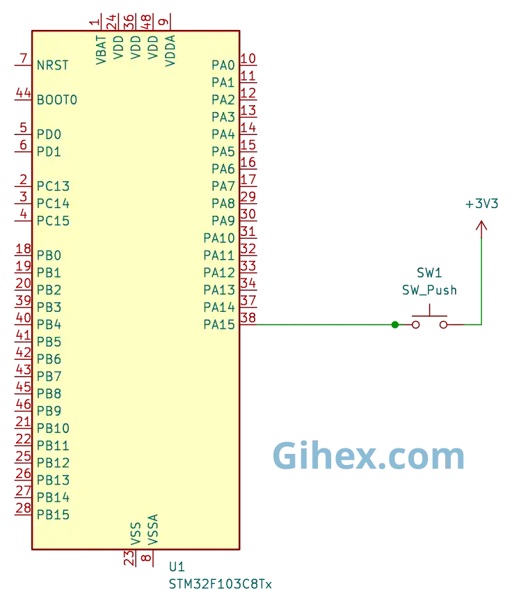
Pin PA15 is configured as an input pull-down. Therefore, when the push button is pressed, the voltage on pin PA15 will rise from 0V to 3.3V; conversely, when it is released, the voltage on pin PA15 will drop from 3.3V to 0V. For a more detailed explanation of the working principle of the circuit schematic used, please refer to the input capture article.
Programming STM32F103C8 Timers with Channel Remap Using Rust
Please create a new Rust project as explained in this article. Next, open the Cargo.toml file and define a new binary executable named ’ timer-channel-remap ’ by adding the following code:
1[[bin]]
2name = "timer-channel-remap"
3path = "src/main.rs"
4test = false
5bench = false
Next, open the src/main.rs file and fill it with the following code:
Rust
 1#![no_std]
 2#![no_main]
 3
 4use core::sync::atomic::{AtomicU32, Ordering};
 5
 6use defmt_rtt as _;
 7use panic_probe as _;
 8
 9use cortex_m_rt::entry;
10use stm32f1xx_hal::{
11    flash::FlashExt,
12    pac::{self, interrupt},
13    prelude::*,
14    rcc::{Config, RccExt},
15    time::Hertz,
16    timer::{Event, Remap, Tim2PartialRemap1, Timer},
17};
Inform the Rust compiler to not use the standard library and to run the program without an operating system.
Then, define the libraries (crates) to be used in the project:
- The
atomiclibrary is used to define global variables so they can be accessed from both the main loop block and the interrupt functions. - The
cortex_m_rtlibrary/crate is used to define the program’s entry point and handle the startup process. defmt_rttis used to send logging data to a PC/laptop using the Real-Time Transfer (RTT) protocol.- The
stm32f1xx_hallibrary allows us to access the STM32F103C8 microcontroller peripherals safely. panic_probeis used to handle runtime errors and automatically send error logs to the host PC/laptop.
Rust
1static NUMB_OVERFLOW: AtomicU32 = AtomicU32::new(0);Create a global variable named NUMB_OVERFLOW to store the number of times the timer experiences an overflow. Here, we use the AtomicU32 variable type so that the variable can be safely accessed from both the main loop block and the Interrupt Service Routine (ISR) block.
In the main function, add the following code:
Rust
1defmt::println!("STM32F103C8 Timer Channel Pin Remap");Send a message to the PC/laptop to identify the program as a timer with channel remapping.
Rust
 1let dp = pac::Peripherals::take().unwrap();
 2
 3let mut flash = dp.FLASH.constrain();
 4
 5let rcc = dp.RCC.constrain();
 6
 7let clock_config = Config::default()
 8    .use_hse(Hertz::MHz(8))
 9    .sysclk(Hertz::MHz(72))
10    .hclk(Hertz::MHz(72))
11    .pclk1(Hertz::MHz(36));
12
13let mut clocks = rcc.freeze(clock_config, &mut flash.acr);
Configure the clock to use an 8 MHz external clock, then set the System clock to 72 MHz, the Advanced High-performance Bus (AHB) peripheral clock to 72 MHz, and the Advanced Peripheral Bus 1 (APB1) clock to 36 MHz. Consequently, the Timer 2 clock frequency will be 72 MHz.
Rust
1let mut gpioa = dp.GPIOA.split(&mut clocks);
2let gpiob = dp.GPIOB.split(&mut clocks);
Accessing the GPIO Port A and GPIO Port B peripherals.
Rust
1let mut afio = dp.AFIO.constrain(&mut clocks);Accessing the Alternate Function Input Output (AFIO) peripheral, which will be used to perform the Timer 2 remapping.
Rust
1let (pa15, _pb3, _pb4) = afio.mapr.disable_jtag(gpioa.pa15, gpiob.pb3, gpiob.pb4);Disabling the JTAG feature so that pin PA15 can be used as a standard input/output or for other alternate functions.
Note: By default, the JTAG peripheral feature is enabled for debugging purposes. Therefore, if we want to use the pins assigned to JTAG (pins PA15, PB3, and PB4), we must disable the JTAG feature first.
Rust
1let pa15 = pa15.into_pull_down_input(&mut gpioa.crh);Configuring pin PA15 as an input pull-down. Consequently, by default, pin PA15 will be connected to GND (0V).
Rust
1Tim2PartialRemap1::remap(&mut afio.mapr);Performing a Partial Remap 1 on Timer 2 for the GPIO pins. Consequently, Channel 1 originally connected to pin PA0 is now connected to pin PA15, and Channel 2 originally connected to pin PA1 is now connected to pin PB3. Meanwhile, Channels 3 and 4 remain connected to their default pins.
Rust
1let timer2 = Timer::new(dp.TIM2, &mut clocks);
2
3unsafe {
4    pac::NVIC::unmask(interrupt::TIM2);
5}
Accessing the Timer 2 peripheral and enabling the Timer 2 interrupt within the NVIC (Nested Vectored Interrupt Controller).
Rust
1let mut counter = timer2.counter_hz();Setting up Timer 2 as a counter.
Rust
1counter.listen(Event::Update);Enabling the update event interrupt for Timer 2 on the STM32F103C8.
Rust
1let timer_register = unsafe { &*pac::TIM2::ptr() };
2
Access the Timer 2 register pointer of the STM32F103C8 directly.
Rust
1timer_register.ccmr1_input().modify(|_, w| w.cc1s().ti1());
2timer_register.ccmr1_input().modify(|_, w| w.cc2s().ti1());
Configure Channel 1 and Channel 2 as input capture. Then, both Channel 1 and Channel 2 will be connected to the same pin, which is pin PA15 (TI1), as it has been remapped using Partial Remap 1.
Rust
1timer_register
2    .ccmr1_input()
3    .modify(|_, w| w.ic1f().fck_int_n8());
4timer_register
5    .ccmr1_input()
6    .modify(|_, w| w.ic2f().fck_int_n8());
Enable the digital filter for Channel 1 and Channel 2 on Timer 2 to reduce debouncing.
Rust
1timer_register.ccer().modify(|_, w| w.cc1e().set_bit());
2timer_register.ccer().modify(|_, w| w.cc2e().set_bit());
Enable input capture for Channel 1 and Channel 2 on Timer 2.
Rust
1timer_register.ccer().modify(|_, w| w.cc1p().clear_bit());
2timer_register.ccer().modify(|_, w| w.cc2p().set_bit());
Configure Channel 1 on Timer 2 to detect the Rising edge, while Channel 2 on Timer 2 is configured to detect the Falling edge
Rust
1counter.start_raw(7199, 65535);Start Timer 2 with a prescaler of 7199 and an Auto-Reload Register (ARR) value of 65535. Timer frequency become 10 KHz.
Rust
1let mut start_press_tick = 0u16;
2
3let mut is_pressed = false;
Create variables to store the tick value when the push button is first pressed and to store the current status of the push button.
Rust
1loop {
2
3}
Create a loop block to run the main program continuously
Inside the loop block, we populate it with the following code:
Rust
 1if counter.get_interrupt().contains(Event::C1) {
 2    let captured_tick = timer_register.ccr1().read().ccr().bits() as u16;
 3
 4    let pin_is_high = pa15.is_high();
 5
 6    if pin_is_high && !is_pressed {
 7        start_press_tick = captured_tick;
 8        NUMB_OVERFLOW.store(0, Ordering::SeqCst);
 9
10        is_pressed = true;
11        defmt::println!("--- Button Pressed ---");
12            defmt::println!("start: {}", start_press_tick);
13    }
14    counter.clear_interrupt(Event::C1);
15}
Inside the loop block, we check for the capture/compare event on Channel 1. If a capture/compare event occurs, indicating a rising edge on pin PA15, we retrieve the value from the Timer 2 Capture/Compare Register 1 (CCR1). Next, check the status of pin PA15. If pin PA15 is HIGH and the is_pressed variable is false, then update the start_press_tick variable with the captured tick value, reset the NUMB_OVERFLOW global variable to 0, and set the is_pressed variable to true. Finally, ensure the Channel 1 capture/compare interrupt flag is cleared, even though it is typically cleared automatically."
Rust
 1if counter.get_interrupt().contains(Event::C2) {
 2    let captured_tick = timer_register.ccr2().read().ccr().bits() as u16;
 3
 4    let pin_is_high = pa15.is_high();
 5    if !pin_is_high && is_pressed {
 6        let total_overflow = NUMB_OVERFLOW.load(Ordering::SeqCst);
 7
 8        let total_tick =
 9        (total_overflow * 65536) + captured_tick as u32 - start_press_tick as u32;
10
11        defmt::println!(
12            "end: {} | total_overflow: {}",
13            captured_tick,
14            total_overflow
15        );
16        defmt::println!("press long: {} ms", total_tick as f32 / 10f32);
17        defmt::println!("----------------------");
18        is_pressed = false;
19    }
20
21counter.clear_interrupt(Event::C2);
22}
Check for the capture/compare event on Channel 2. If a capture/compare event occurs, indicating a falling edge on pin PA15, retrieve the value from the Timer 2 Capture/Compare Register 2 (CCR2).
Next, check the status of pin PA15. If pin PA15 is LOW and the is_pressed variable is true, calculate the total ticks elapsed while the push button was pressed. Then, use the total ticks to calculate the press duration and set the is_pressed variable to false. Finally, ensure the Channel 2 capture/compare interrupt flag is cleared, even though it is typically cleared automatically.
Next, create the Interrupt Service Routine (ISR) that the CPU will execute whenever a Timer 2 interrupt occurs. The following is the interrupt function we will be using.
Rust
 1#[interrupt]
 2fn TIM2() {
 3    let timer_register = unsafe { &*pac::TIM2::ptr() };
 4
 5    // check update interrupt flag
 6    if timer_register.sr().read().uif().bit_is_set() {
 7        // Increment overflow count
 8        NUMB_OVERFLOW.fetch_add(1, Ordering::SeqCst);
 9        // Clear update interrupt flag
10        timer_register.sr().modify(|_, w| w.uif().clear_bit());
11    }
12}
Create the interrupt function (ISR) for Timer 2. Inside the function, we check the update interrupt flag. If the interrupt is triggered by an update event, we increment the NUMB_OVERFLOW global variable by 1, and subsequently clear the update interrupt flag bit.
  1#![no_std]
  2#![no_main]
  3
  4use core::sync::atomic::{AtomicU32, Ordering};
  5
  6use defmt_rtt as _;
  7use panic_probe as _;
  8
  9use cortex_m_rt::entry;
 10use stm32f1xx_hal::{
 11    flash::FlashExt,
 12    pac::{self, interrupt},
 13    prelude::*,
 14    rcc::{Config, RccExt},
 15    time::Hertz,
 16    timer::{Event, Remap, Tim2PartialRemap1, Timer},
 17};
 18
 19static NUMB_OVERFLOW: AtomicU32 = AtomicU32::new(0);
 20
 21#[entry]
 22fn main() -> ! {
 23    defmt::println!("STM32F103C8 Timer Channel Pin Remap");
 24
 25    let dp = pac::Peripherals::take().unwrap();
 26
 27    let mut flash = dp.FLASH.constrain();
 28
 29    let rcc = dp.RCC.constrain();
 30
 31    let clock_config = Config::default()
 32        .use_hse(Hertz::MHz(8))
 33        .sysclk(Hertz::MHz(72))
 34        .hclk(Hertz::MHz(72))
 35        .pclk1(Hertz::MHz(36));
 36
 37    let mut clocks = rcc.freeze(clock_config, &mut flash.acr);
 38
 39    let mut gpioa = dp.GPIOA.split(&mut clocks);
 40    let gpiob = dp.GPIOB.split(&mut clocks);
 41
 42    let mut afio = dp.AFIO.constrain(&mut clocks);
 43
 44    let (pa15, _pb3, _pb4) = afio.mapr.disable_jtag(gpioa.pa15, gpiob.pb3, gpiob.pb4);
 45
 46    let pa15 = pa15.into_pull_down_input(&mut gpioa.crh);
 47
 48    // Use remap partial 1 for Timer 2
 49    Tim2PartialRemap1::remap(&mut afio.mapr);
 50
 51    let timer2 = Timer::new(dp.TIM2, &mut clocks);
 52
 53    unsafe {
 54        pac::NVIC::unmask(interrupt::TIM2);
 55    }
 56
 57    let mut counter = timer2.counter_hz();
 58
 59    counter.listen(Event::Update);
 60
 61    let timer_register = unsafe { &*pac::TIM2::ptr() };
 62
 63    timer_register.ccmr1_input().modify(|_, w| w.cc1s().ti1());
 64    timer_register.ccmr1_input().modify(|_, w| w.cc2s().ti1());
 65
 66    timer_register
 67        .ccmr1_input()
 68        .modify(|_, w| w.ic1f().fck_int_n8());
 69    timer_register
 70        .ccmr1_input()
 71        .modify(|_, w| w.ic2f().fck_int_n8());
 72
 73    timer_register.ccer().modify(|_, w| w.cc1e().set_bit());
 74    timer_register.ccer().modify(|_, w| w.cc2e().set_bit());
 75
 76    timer_register.ccer().modify(|_, w| w.cc1p().clear_bit());
 77    timer_register.ccer().modify(|_, w| w.cc2p().set_bit());
 78
 79    counter.start_raw(7199, 65535);
 80
 81    let mut start_press_tick = 0u16;
 82
 83    let mut is_pressed = false;
 84
 85    loop {
 86        if counter.get_interrupt().contains(Event::C1) {
 87            let captured_tick = timer_register.ccr1().read().ccr().bits() as u16;
 88
 89            let pin_is_high = pa15.is_high();
 90
 91            if pin_is_high && !is_pressed {
 92                start_press_tick = captured_tick;
 93                NUMB_OVERFLOW.store(0, Ordering::SeqCst);
 94
 95                is_pressed = true;
 96                defmt::println!("--- Button Pressed ---");
 97                defmt::println!("start: {}", start_press_tick);
 98            }
 99            counter.clear_interrupt(Event::C1);
100        }
101
102        if counter.get_interrupt().contains(Event::C2) {
103            let captured_tick = timer_register.ccr2().read().ccr().bits() as u16;
104
105            let pin_is_high = pa15.is_high();
106            if !pin_is_high && is_pressed {
107                let total_overflow = NUMB_OVERFLOW.load(Ordering::SeqCst);
108
109                let total_tick =
110                    (total_overflow * 65536) + captured_tick as u32 - start_press_tick as u32;
111
112                defmt::println!(
113                    "end: {} | total_overflow: {}",
114                    captured_tick,
115                    total_overflow
116                );
117                defmt::println!("press long: {} ms", total_tick as f32 / 10f32);
118                defmt::println!("----------------------");
119                is_pressed = false;
120            }
121
122            counter.clear_interrupt(Event::C2);
123        }
124    }
125}
126
127#[interrupt]
128fn TIM2() {
129    let timer_register = unsafe { &*pac::TIM2::ptr() };
130
131    // check update interrupt flag
132    if timer_register.sr().read().uif().bit_is_set() {
133        // Increment overflow count
134        NUMB_OVERFLOW.fetch_add(1, Ordering::SeqCst);
135        // Clear update interrupt flag
136        timer_register.sr().modify(|_, w| w.uif().clear_bit());
137    }
138}
Using the ST-Link USB Downloader and Debugger, connect the Blue Pill board (STM32F103C8 microcontroller) to your PC or laptop as described in this article. After that, execute the program by running the command ‘cargo run --bin timer-channel-remap’ in the VSCode terminal. The following is the output when the program is executed:
By using the Timer pin remapping feature, we can change the GPIO channel pin paths to other supported pins. In this tutorial, we are rerouting the Timer 2 channel 1 GPIO pin from PA0 to PA15 by using partial remap 1.
Source Code
The Rust project source code used in this tutorial can be accessed at the Github repository.
If you encounter any issues while following this tutorial, have questions, or wish to provide feedback and suggestions, please contact us via the contact page.