STM32 ADC + Rust: Reading Multiple Channel Groups Automatically
In the previous article, we discussed the ADC scan mode on the Blue Pill (STM32F103C8), covering everything from an introduction to scan mode to program examples using Rust. In the STM32F103C8’s ADC scan mode, we can only define a single group of channels to be converted with one command from the CPU. But what if we want to convert multiple groups of channels? This is where discontinuous conversion comes into play. By using scan mode combined with discontinuous conversion, the channel group is divided into several subgroups based on a specified number of channels. Each time the CPU commands the ADC to perform a conversion, the ADC will convert one subgroup, starting from the first.
As explained in the previous article, accessing the STM32F103C8 ADC with scan mode and discontinuous conversion is safest when using Direct Memory Access (DMA). Although the stm32f1xx_hal crate provides methods for discontinuous conversion, in reality, we still need to access the ADC registers directly to ensure the resulting data is reliable. This is indeed somewhat tricky, but we will explain in detail below why this is necessary.
Introduction to ADC Scan Mode with Discontinuous Conversion on the Blue Pill (STM32F103C8)
Discontinuous conversion functions to divide a channel group into several subgroups. Every time the CPU commands the ADC to perform a conversion, one subgroup will be converted, starting from the first subgroup. Each time the ADC finishes converting a channel, it sets the EOC (End of Conversion) bit in the SR register to 1. To activate discontinuous conversion, we need to set the DISCEN bit in the CR1 register to 1 and adjust the DISCNUM bits according to the desired number of channels per subgroup. The maximum number of channels allowed in a single subgroup is 8.
The DISCNUM bit field consists of 3 bits, meaning it can only hold values from 0 to 7. The DISCNUM value represents the number of channels in the subgroup minus one (n−1). If we want a subgroup to contain 1 channel, we must set the DISCNUM value to 0 (1−1=0). Likewise, if we want a subgroup to contain 3 channels, we must set the DISCNUM value to 2 (3−1=2). Below is an illustration of discontinuous conversion:
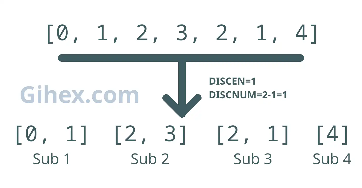
In that figure, we have created a channel group consisting of 7 sequences. When discontinuous conversion is activated and DISCNUM is set to 1 (meaning each subgroup consists of 2 channels), subgroups 1 through 3 will contain 2 channels each, while the final subgroup will contain 1 channel (the remainder). The following is the ADC conversion process using discontinuous conversion:
- The CPU commands the ADC to convert: The ADC converts Subgroup 1.
- The CPU gives a second command: The ADC converts Subgroup 2.
- The CPU gives a third command: The ADC converts Subgroup 3.
- The CPU gives a fourth command: The ADC converts the final subgroup (Subgroup 4).
- If the CPU commands the ADC again: The ADC will start over and convert Subgroup 1 again.
Hardware Preparation
Since we are still using ADC scan mode, the hardware used in this article remains the same as in the previous one, including: the Blue Pill board (STM32F103C8), ST-Link USB Downloader/Debugger, potentiometers, a breadboard, and several jumper wires (female-to-female and male-to-male). Please read the explanation of the component functions in this article and this one. You may use more potentiometers, just need to adjust the circuit and the program code accordingly.
Analog Input Scan Mode with Discontinuous Conversion on the Blue Pill (STM32F103C8) Using Rust
This tutorial will focus on using scan mode with discontinuous conversion; standard scan mode and scan mode with continuous conversion were covered in previous articles. We will attempt to read the input voltage values from two potentiometers using two channels, PA0 and PA1, and then display their digital values on a PC/laptop terminal.
Blue Pill (STM32F103C8) circuit with Potentiometers for Scan Mode
First, please build the circuit on the breadboard according to the following schematic; we are using pin PA0 (channel 0) and pin PA1 (channel 1) as the analog inputs:
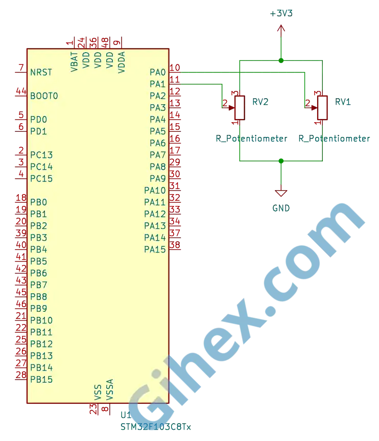
You may use other channels according to your preference, just ensure that you adjust the program accordingly. If you use more potentiometers, please follow the schematic: connect Pin 1 of the potentiometer to GND , Pin 2 to the ADC channel being used, and Pin 3 to 3.3V.
Programming the Blue Pill (STM32F103C8) as an Analog Input in Scan Mode with Discontinuous Conversion
We will create a channel group consisting of 6 channel sequences, which will be divided into two subgroups where each subgroup consists of 3 channels. Therefore, to convert all channels, two commands from the CPU are required.
First, create a new Rust project according to this article. Add a new binary named ‘scan-mode-discontinuous’: open the Cargo.toml file and fill it with the following code to define the new executable binary:
1[[bin]]
2name = "scan-mode-discontinuous"
3path = "src/main.rs"
4test = false
5bench = false
Open the src/main.rs file and change its contents to the following code to inform the compiler that we are not using the standard library and that the program is not running on an operating system:
1#![no_std]
2#![no_main]
Defining all the libraries/crates that will be used:
Rust
 1use cortex_m_rt::entry;
 2use defmt_rtt as _;
 3use panic_probe as _;
 4
 5use stm32f1xx_hal::{
 6    adc::{self, Adc, SetChannels},
 7    gpio::{Analog, PA0, PA1},
 8    pac::{self, ADC1},
 9    prelude::*,
10    rcc::Config,
11    time::Hertz,
12};
The cortex_m_rt library/crate defines the program’s entry point and handles the startup process. defmt_rtt is used to send logging data to a PC/laptop using the Real-Time Transfer (RTT) protocol. The stm32f1xx_hal library enables safe access to the STM32F103C8 microcontroller peripherals. panic_probe is used to handle runtime errors, and it will automatically transmit the error logs to the host PC/laptop.
Next, create a new struct to hold all the channels within a single group.
Rust
1struct AdcChannels(PA0<Analog>, PA1<Analog>);Since we will be using pins PA0 and PA1, we are creating a tuple struct named AdcChannels with the fields PA0 and PA1 , both of which are of the Analog type. If you use other channels, please adjust them here, or if you are using more channels, please add them here.
Implementing the SetChannel trait with our created struct type for the ADC, which is of type ADC1.
Rust
 1impl SetChannels<AdcChannels> for Adc<ADC1> {
 2    fn set_samples(&mut self) {
 3        self.set_channel_sample_time(0, adc::SampleTime::T_55);
 4        self.set_channel_sample_time(1, adc::SampleTime::T_55);
 5    }
 6
 7    fn set_sequence(&mut self) {
 8        self.set_regular_sequence(&[0, 1, 0, 1, 0, 1]);
 9        self.set_discontinuous_mode(Some(2));
10    }
11}
Here, we set the sample time for each channel to 55.5 cycles. Next, we create a channel group with 6 channel sequences: [0, 1, 0, 1, 0, 1]. Using the set_discontinuous_mode method, we set the DISCNUM value to 2, so each subgroup will contain 3 channels, specifically [0, 1, 0] and [1, 0, 1].
Warning: When using the
set_discontinuous_modemethod, ensure that you fill thechannels_countparameter with the number of channels per subgroup minus one (n−1). This is because the value of that parameter is written directly into the DISCNUM bits. A common mistake is to assume the parameter should be filled with the actual number of channels in a subgroup. Additionally, ensure you do not use a value greater than 7, as this will result in an undefined value forDISCNUM.
Next, create the main function.
Rust
1#[entry]
2fn main() -> ! {
3    // Access peripherals,
4    // perform setup,
5    // run main code within loop block
6}
Inside the main function, we will access the Blue Pill (STM32F103C8) peripherals, then perform the configuration setup for the clock , GPIO , and other components. We will also create the main program logic within the loop block.
Inside the main function, add the following code:
Rust
1defmt::println!("ADC Scan Mode Discontinuous");
2
3let dp = pac::Peripherals::take().unwrap();
4let cp = pac::CorePeripherals::take().unwrap();
Sending a message to the PC/laptop terminal while simultaneously marking the start of the scan mode with discontinuous conversion program. The next line serves to access the STM32F103C8 microcontroller peripherals and the Cortex-M3 CPU peripherals (CorePeripherals).
Rust
1let mut flash = dp.FLASH.constrain();
2let rcc = dp.RCC.constrain();
Accessing the Flash peripherals and the Reset and Clock Control (RCC) peripherals.
Rust
1let clock_cfgr = Config::default()
2        .use_hse(Hertz::MHz(8))
3        .sysclk(Hertz::MHz(72))
4        .hclk(Hertz::MHz(72))
5        .adcclk(Hertz::MHz(9));
6
7let mut clocks = rcc.freeze(clock_cfgr, &mut flash.acr);
Creating a clock configuration that uses the external clock ( use_hse ) with an 8 MHz frequency, setting the System clock ( sysclk ) to 72 MHz, the Bus clock ( hclk ) to 72 MHz, and the ADC clock ( adcclk ) to 9 MHz. Then, applying this clock configuration to the RCC and adjusting the flash memory wait states.
Rust
1let mut delay = cp.SYST.delay(&clocks.clocks);Using the System Timer to create a delay.
Rust
1 let mut gpioa = dp.GPIOA.split(&mut clocks);
2
3let potentio_1 = gpioa.pa0.into_analog(&mut gpioa.crl);
4let potentio_2 = gpioa.pa1.into_analog(&mut gpioa.crl);
Accessing the GPIO Port A peripherals and configuring pins PA0 and PA1 as analog inputs, which will be used to read the input voltage from the potentiometers.
Rust
1let dma = dp.DMA1.split(&mut clocks);Accessing the peripherals DMA1 (Direct Memory Access) STM32F103C8.
Rust
1let adc1 = adc::Adc::new(dp.ADC1, &mut clocks);Accessing the peripherals ADC1.
Rust
1let adc_channels = AdcChannels(potentio_1, potentio_2);
2
3let adc_scan_dma = adc1.with_scan_dma(adc_channels, dma.1);
Creating a variable from the struct we previously defined, with the fields containing GPIO PA0 ( potentio_1 ) and PA1 ( potentio_2 ) as analog inputs. Next, using the with_scan_dma method to configure ADC1 into scan mode while simultaneously enabling DMA channel 1.
Rust
1let buf = cortex_m::singleton!(: [u16; 6] = [0; 6]).unwrap();Creating a buffer to store the ADC conversion results. We are using six 16-bit unsigned integers because our channel group uses a sequence of 6 channels, if you are using a different number of sequences please adjust accordingly.
Rust
1let mut i = 0u32;Creating a variable to store the total number of times the ADC has converted the entire channel sequence.
Rust
1unsafe {
2    (*pac::ADC1::ptr())
3        .cr2()
4        .modify(|_, w| w.adon().clear_bit());
5}
6let mut transfer = adc_scan_dma.read(buf);
The read method should ideally command the ADC to perform the conversion and prepare the DMA to transfer the results to the buffer. However, in discontinuous conversion mode, the CPU fails to trigger the ADC (the solution is provided below). This part is also quite tricky because, for data reliability, we must disable the ADC (by setting the ADON bit in the CR2 register to 0) before calling the read method; otherwise, the data filled into the buffer may shift or become randomized, failing to match the defined channel sequence.
Note: When the
readmethod is called, theADONbit in the CR2 register will be set to 1 again automatically, so there is no need to manually set that bit back to 1.
Next, create the loop block.
Rust
1loop {
2    // main code
3}
The loop block will execute the main program code repeatedly.
Inside the loop block, add our main program code as follows:
Rust
1for x in 0..2 {
2    // Convert and read ADC value
3}
4i += 1;
Inside the loop block, we create a for loop that runs twice because we have two subgroups. Each time the for loop iterates, one subgroup is converted; once the for loop has run twice, all subgroups have finished their conversion. If you have a different number of subgroups, please adjust accordingly. Next, increment the variable i by 1 every time all subgroups have completed their conversion.
Inside the for loop, add the code to start the conversion and read the ADC values:
Rust
 1unsafe {
 2    (*pac::ADC1::ptr())
 3        .cr2()
 4        .modify(|_, w| w.swstart().set_bit());
 5}
 6delay.delay_ms(1u8);
 7
 8let group = unsafe { (*pac::DMA1::ptr()).ch(0).ndtr().read().ndt().bits() };
 9
10if group == 3 {
11    defmt::println!("Convert subgroup {}: {:?}", x, transfer.peek()[..3]);
12}
13
14if group == 0 {
15    defmt::println!("Convert subgroup {}: {:?}", x, transfer.peek()[3..]);
16            }
17
18if transfer.is_done() {
19    let (recovered_buf, recovered_adc_dma) = transfer.wait();
20    defmt::println!("{} Convert full Data: {:?}", i, recovered_buf);
21
22    unsafe {
23        (*pac::ADC1::ptr())
24            .cr2()
25            .modify(|_, w| w.adon().clear_bit());
26    }
27
28    transfer = recovered_adc_dma.read(recovered_buf);
29}
30
31delay.delay_ms(200u8);
First, start the conversion of the first subgroup by setting the SWSTART bit in the CR2 register to 1 and applying a 1 ms delay. Next, read the value of the NDTR (Number of Data Register) from DMA1. If the NDTR value equals 3, it means 3 ADC data points have been transferred to the buffer, indicating that the first subgroup conversion is complete. Then, use the peek method to retrieve the first 3 data points from the buffer and send them to the PC/laptop terminal. If the NDTR value equals 0, it means all 6 ADC data points have been transferred, indicating that both the first and second subgroups are finished. Subsequently, retrieve the last 3 data points from the buffer and send them to the terminal. Once the buffer is full (all subgroups converted), use the wait method to collect the entire buffer and send it to the terminal.
Next, prepare for the second subgroup conversion. Set the ADON bit in the CR2 register to 0 to ensure reliable readings. Then, call the read method again to reactivate the ADC and prepare the DMA. Apply a 200 ms delay to provide a pause in each iteration. After that, the for loop will restart, setting the SWSTART bit to 1 to trigger the second subgroup conversion.
This process will repeat continuously, ensuring that first subgroup and second subgroup are converted alternately.
Note: In the DMA, every time a single piece of data is transferred to the buffer, the value of the
NDTRregister decrements by one. If the buffer is full, the value of theNDTRregister becomes 0.
In this program, the CPU issues a command to the ADC by setting the SWSTART bit in the CR2 register to 1 every time it is about to convert a subgroup.
1#![no_std]
2#![no_main]
3
4use cortex_m_rt::entry;
5use defmt_rtt as _;
6use panic_probe as _;
7
8use stm32f1xx_hal::{
9 adc::{self, Adc, SetChannels},
10 gpio::{Analog, PA0, PA1},
11 pac::{self, ADC1},
12 prelude::*,
13 rcc::Config,
14 time::Hertz,
15};
16
17struct AdcChannels(PA0<Analog>, PA1<Analog>);
18
19impl SetChannels<AdcChannels> for Adc<ADC1> {
20 fn set_samples(&mut self) {
21 self.set_channel_sample_time(0, adc::SampleTime::T_55);
22 self.set_channel_sample_time(1, adc::SampleTime::T_55);
23 }
24
25 fn set_sequence(&mut self) {
26 self.set_regular_sequence(&[0, 1, 0, 1, 0, 1]);
27 self.set_discontinuous_mode(Some(2));
28 }
29}
30
31#[entry]
32fn main() -> ! {
33 defmt::println!("ADC Scan Mode Discontinuous");
34
35 let dp = pac::Peripherals::take().unwrap();
36
37 let cp = pac::CorePeripherals::take().unwrap();
38
39 let mut flash = dp.FLASH.constrain();
40
41 let rcc = dp.RCC.constrain();
42
43 let clock_cfgr = Config::default()
44 .use_hse(Hertz::MHz(8))
45 .sysclk(Hertz::MHz(72))
46 .hclk(Hertz::MHz(72))
47 .adcclk(Hertz::MHz(9));
48
49 let mut clocks = rcc.freeze(clock_cfgr, &mut flash.acr);
50
51 let mut delay = cp.SYST.delay(&clocks.clocks);
52
53 let mut gpioa = dp.GPIOA.split(&mut clocks);
54
55 let potentio_1 = gpioa.pa0.into_analog(&mut gpioa.crl);
56 let potentio_2 = gpioa.pa1.into_analog(&mut gpioa.crl);
57
58 let dma = dp.DMA1.split(&mut clocks);
59
60 let adc1 = adc::Adc::new(dp.ADC1, &mut clocks);
61
62 let adc_channels = AdcChannels(potentio_1, potentio_2);
63
64 let adc_scan_dma = adc1.with_scan_dma(adc_channels, dma.1);
65
66 let buf = cortex_m::singleton!(: [u16; 6] = [0; 6]).unwrap();
67 let mut i = 0u32;
68
69 unsafe {
70 (*pac::ADC1::ptr())
71 .cr2()
72 .modify(|_, w| w.adon().clear_bit());
73 }
74 let mut transfer = adc_scan_dma.read(buf);
75
76 loop {
77 for x in 0..2 {
78 unsafe {
79 (*pac::ADC1::ptr())
80 .cr2()
81 .modify(|_, w| w.swstart().set_bit());
82 }
83 delay.delay_ms(1u8);
84
85 let group = unsafe { (*pac::DMA1::ptr()).ch(0).ndtr().read().ndt().bits() };
86
87 if group == 3 {
88 defmt::println!("Convert subgroup {}: {:?}", x, transfer.peek()[..3]);
89 }
90
91 if group == 0 {
92 defmt::println!("Convert subgroup {}: {:?}", x, transfer.peek()[3..]);
93 }
94
95 if transfer.is_done() {
96 let (recovered_buf, recovered_adc_dma) = transfer.wait();
97 defmt::println!("{} Convert full Data: {:?}", i, recovered_buf);
98
99 unsafe {
100 (*pac::ADC1::ptr())
101 .cr2()
102 .modify(|_, w| w.adon().clear_bit());
103 }
104
105 transfer = recovered_adc_dma.read(recovered_buf);
106 }
107
108 delay.delay_ms(200u16);
109 }
110 i += 1;
111 }
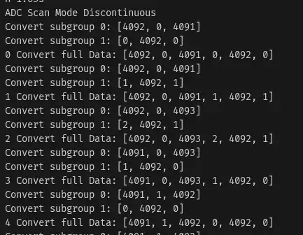
112}Run the program using the command cargo run --bin scan-mode-discontinuous in the terminal. The following are the results of the scan mode program with discontinuous conversion:
In these results, it can be seen that the first iteration of the for loop converts subgroup 0 ([0, 1, 0]), resulting in the first three data points in the buffer containing the ADC values [channel 0, channel 1, channel 0]. The second iteration of the for loop converts subgroup 1 ([1, 0, 1]), filling the last three data points in the buffer with the ADC values [channel 1, channel 0, channel 1]. All subgroups are fully converted within two conversion commands from the CPU.
Issues and Sourc Code
The following are several issues we encountered while creating this tutorial:
- The data in the DMA buffer was filled randomly and did not match the defined channel sequence: Through debugging, we discovered that the
DISCNUMbit in the CR1 register was set to 3 (it should have been 2) because we had set theset_discontinuous_modeparameter to 3 (for 3 channels per subgroup). After correcting this by changing the value to 2, the data in the DMA buffer still appeared to be shifted. To resolve this, we set theADONbit to 0 every time before the read method is called.
The source code used in this article can be found in the GitHub repository.
If you encounter any other obstacles, have questions, or would like to provide criticism and suggestions, please contact us through the contact page.