Blue Pill (STM3F103C8): ADC Continuous Conversion With Rust
Before reading this article, please read Getting Started with ADC on STM32F103C8 (Blue Pill) using Rust first. That article discusses analog inputs and the Analog to Digital Converter (ADC) on the Blue Pill (STM32F103C8), as well as a program example for Single Conversion mode using Rust. In this tutorial, we will continue by exploring the ADC on the Blue Pill (STM32F103C8) using continuous conversion mode with Rust.
The difference between the STM32F103C8 ADC single conversion mode and continuous conversion mode lies in the conversion process. In single conversion mode, the ADC performs a conversion only when it receives a command from the CPU and stops once it is finished. In contrast, in continuous conversion mode, after the ADC receives the initial conversion command from the CPU, it does not stop upon completion; instead, it performs conversions repeatedly and continuously without waiting for further commands from the CPU.
Hardware Preparation
The hardware used in this tutorial is the same as in the previous article. The hardware includes: the Blue Pill (STM32F103C8), an ST-Link USB Downloader/Debugger, a potentiometer, a breadboard, and several jumper wires (female-to-female and male-to-male). Explanations regarding their respective functions can be found in the previous article and in the article regarding the STM32F103C8 setup with Rust on Linux.
Analog Input in Continuous Conversion Mode on the Blue Pill (STM32F103C8) with Rust
Just like with single conversion, we can also implement continuous conversion using the polling method, Direct Memory Access (DMA), and Interrupts:
- Continuous Conversion Poll: The ADC only starts converting when commanded by the CPU. Once the initial conversion is complete, the ADC will continue to convert repeatedly without waiting for further commands from the CPU. The CPU reads the conversion data in the main program without needing to re-trigger the ADC.
- Continuous Conversion DMA: The ADC starts converting when commanded by the CPU, and the conversion results are then sent directly to RAM (DMA buffer). While the conversion process is running, the CPU can perform other tasks; once the DMA buffer is filled, the CPU reads the results from that buffer. The ADC performs conversions continuously, and with DMA, it automatically fills the buffer without waiting for further CPU commands.
- Continuous Conversion Interrupt: The ADC starts converting when commanded by the CPU. Once a conversion is finished, the ADC notifies the CPU, which then pauses its main program to execute the ISR (Interrupt Service Routine). The ADC continues to convert repeatedly without needing new commands from the CPU. If conversions are performed too frequently using this method, the CPU will be constantly interrupted, which can lead to high CPU overhead.
Just like the previous article, we will attempt to read the input voltage value from a potentiometer using the GPIO PA0 pin, and then display the resulting digital value on a PC/laptop terminal.
The Blue Pill (STM32F103C8) and Potentiometer Circuit
The circuit used in this tutorial is the same as in the previous article; we will utilize a potentiometer as a voltage divider device that acts as a sensor. Below is the schematic diagram of the circuit used:
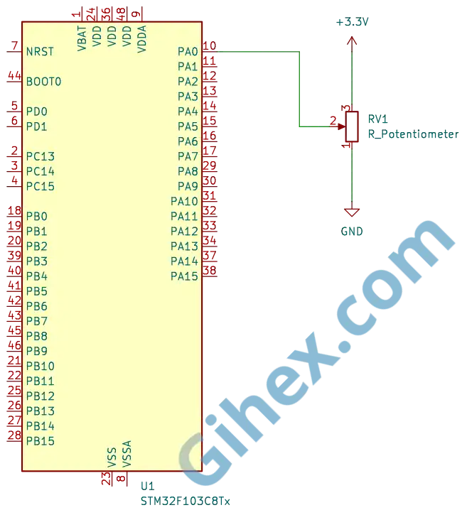
Further explanation regarding the circuit can be found in the previous article. Please assemble the circuit on a breadboard according to the schematic diagram before we proceed to write the Rust code.
Programming the Blue Pill (STM32F103C8) as an Analog Input with Continuous Conversion Polling
First, let’s create a new Rust project as described in this article. Open the Cargo.toml file and add the following code to define a new executable binary named ‘continuous-conversion-poll’:
1[[bin]]
2name = "continuous-conversion-poll"
3path = "src/main.rs"
4test = false
5bench = false
Next, we will write the Rust code for continuous conversion polling. Since the stm32f1xx_hal crate does not provide a specific method to access the ADC in continuous conversion polling mode, we will implement it by accessing the ADC registers directly.
Let’s open the src/main.rs file and change its content according to the following code to inform the compiler that we are not using the standard library and that the program is not running on top of an operating system:
1#![no_std]
2#![no_main]
Next, add the following code:
 1use cortex_m_rt::entry;
 2
 3use defmt_rtt as _;
 4use panic_probe as _;
 5use stm32f1xx_hal::{
 6    adc::{self, ChannelTimeSequence},
 7    flash::FlashExt,
 8    gpio::{GpioExt, PinExt},
 9    hal::delay::DelayNs,
10    pac,
11    rcc::{Config, RccExt},
12    time::Hertz,
13    timer::SysTimerExt,
14};
The code above serves to define the libraries used. The cortex-m-rt crate, handles the startup sequence, such as resetting the stack pointer and initializing the memory before your code runs. defmt-rtt is used to help send data to your host computer via the RTT (Real-Time Transfer) protocol. The stm32f1xx_hal library allows us safely to access the peripherals of the STM32F103C8 microcontroller.
Next, we will create the main function
1#[entry]
2fn main() -> ! {
3    // Our code
4    // ...
5}
We apply the entry macro to the main function to specify that the program execution starts from here. Inside this main function, we will access the STM32F103C8 peripherals and implement the program logic
Inside the main function, we will insert the following code:
1defmt::println!("Input Analog Mode Continuous Poll");Send messages to the PC/Laptop, while simultaneously marking the program as being in Continuous Conversion Poll mode.
1let dp = pac::Peripherals::take().unwrap();
2let cp = pac::CorePeripherals::take().unwrap()
This serves to access the STM32F103C8 peripherals and the Cortex-M3 CPU peripherals, storing them in the variables dp and cp respectively.
1let mut flash = dp.FLASH.constrain();
2let rcc = dp.RCC.constrain();
Accessing the flash peripheral and the reset & clock control (RCC) peripheral. The Flash peripheral is required to adjust the wait states during clock configuration. The RCC peripheral is used to configure the system clock of the STM32F103C8 microcontroller.
1let clock_cfgr = Config::default()
2        .use_hse(Hertz::MHz(8))
3        .sysclk(Hertz::MHz(72))
4        .hclk(Hertz::MHz(72))
5        .adcclk(Hertz::MHz(9));
6
7let mut clocks = rcc.freeze(clock_cfgr, &mut flash.acr);
Configuring the clock to use an external source ( use_hse ) with a frequency of 8 MHz, setting the System clock ( sysclk ) to 72 MHz, the Bus clock ( hclk ) to 72 MHz, and the ADC clock ( adcclk ) to 9 MHz. These configurations are then applied to the RCC, while simultaneously adjusting the flash memory wait states.
1let mut delay = cp.SYST.delay(&clocks.clocks);Creating a delay instance using the System Timer. This delay will be used to provide wait times during program execution.
1let mut gpioa = dp.GPIOA.split(&mut clocks);
2let potentio = gpioa.pa0.into_analog(&mut gpioa.crl);
Accessing the GPIO Port A peripheral and configuring pin PA0 as an analog input, which will be used to read the input voltage from the potentiometer.
1let mut adc1 = adc::Adc::new(dp.ADC1, &mut clocks);
2adc1.set_continuous_mode(true);
Accessing the ADC1 peripheral and setting it to continuous conversion mode.
1let adc_reg = unsafe { &*pac::ADC1::ptr() };Accessing the ADC1 register pointer directly so that we can modify its register bits to configure it for continuous conversion mode using the polling method.
1adc_reg.cr2().modify(|_, w| w.adon().clear_bit());Setting the ADON bit in the CR2 register to 0 to disable the ADC, ensuring safety while configuring other register bits
1adc_reg.cr1().modify(|_, w| w.scan().clear_bit());Disabling Scan Conversion mode since we will only be using a single channel. The SCAN bit in the CR1 register will be set to 0.
1adc_reg.cr1().modify(|_, w| w.discen().clear_bit());Disabling Discontinuous Conversion mode to allow continuous conversion mode to function properly. Discontinuous Conversion mode is automatically enabled when we call the Adc::new function. The DISCEN bit in the CR1 register will be set to 0.
1adc_reg.sqr1().modify(|_, w| unsafe { w.l().bits(0b0000) });Determining the number of channels to be used. Since we are using only 1 channel, the value is set to 0 (number of channels-1).
1adc_reg.cr2().modify(|_, w| w.adon().set_bit());Re-enabling ADC1. The ADON bit in the CR2 register will be set to 1.
1adc_reg
2    .sqr3()
3    .modify(|_, w| unsafe { w.sq1().bits(potentio.pin_id()) });
Setting the ADC channel to be read. The command potentio.pin_id() will return the pin ID of pin PA0, which is 0.
1// adc_reg.cr2().modify(|_, w| w.adon().set_bit());
2adc_reg.cr2().modify(|_, w| w.swstart().set_bit());
Starting the conversion by setting the SWSTART bit in the CR2 register to 1. Alternatively, you can also start the conversion by setting the ADON bit in the CR2 register to 1 once more. You may choose either method according to your preference.
1loop {
2    // main  code
3    // executed repeatedly
4    // ...
5}
This is the loop block. Inside this block, we will place our main program, ensuring it will be executed continuously and repeatedly.
1if adc_reg.sr().read().eoc().bit_is_set() {
2    // Read ADC value
3}
We place this code inside the loop block to be executed repeatedly. This code serves to read the EOC bit of the SR register, if its value is 1 (conversion complete), then the command inside the if block is executed.
1let val = adc_reg.dr().read().bits();
2let voltage = (val as f32 / 4095.0) * 3.3;
3defmt::println!("Raw Avg: {} | Volt: {}V", val, voltage);
4delay.delay_ms(500);
Inside the if block, we include this code to read the ADC value from the DATA field of the DR register and store it in the val variable. It then calculates the input voltage level and stores it in the voltage variable. Subsequently, the values of the val and voltage variables are sent to the PC/laptop terminal, followed by a 500 ms delay.
 1#![no_std]
 2#![no_main]
 3
 4use cortex_m_rt::entry;
 5
 6use defmt_rtt as _;
 7use panic_probe as _;
 8use stm32f1xx_hal::{
 9    adc::{self, ChannelTimeSequence},
10    flash::FlashExt,
11    gpio::{GpioExt, PinExt},
12    hal::delay::DelayNs,
13    pac,
14    rcc::{Config, RccExt},
15    time::Hertz,
16    timer::SysTimerExt,
17};
18
19#[entry]
20fn main() -> ! {
21    defmt::println!("Input Analog Mode Continuous Poll");
22
23    let dp = pac::Peripherals::take().unwrap();
24
25    let cp = pac::CorePeripherals::take().unwrap();
26
27    let mut flash = dp.FLASH.constrain();
28    let rcc = dp.RCC.constrain();
29
30    let clock_cfgr = Config::default()
31        .use_hse(Hertz::MHz(8))
32        .sysclk(Hertz::MHz(72))
33        .hclk(Hertz::MHz(72))
34        .adcclk(Hertz::MHz(9));
35
36    let mut clocks = rcc.freeze(clock_cfgr, &mut flash.acr);
37
38    let mut delay = cp.SYST.delay(&clocks.clocks);
39
40    let mut gpioa = dp.GPIOA.split(&mut clocks);
41    let potentio = gpioa.pa0.into_analog(&mut gpioa.crl);
42
43    let mut adc1 = adc::Adc::new(dp.ADC1, &mut clocks);
44
45    adc1.set_continuous_mode(true);
46
47    let adc_reg = unsafe { &*pac::ADC1::ptr() };
48
49    adc_reg.cr2().modify(|_, w| w.adon().clear_bit());
50
51    adc_reg.cr1().modify(|_, w| w.scan().clear_bit());
52
53    adc_reg.cr1().modify(|_, w| w.discen().clear_bit());
54
55    adc_reg.sqr1().modify(|_, w| unsafe { w.l().bits(0b0000) });
56
57    adc_reg.cr2().modify(|_, w| w.adon().set_bit());
58
59    adc_reg
60        .sqr3()
61        .modify(|_, w| unsafe { w.sq1().bits(potentio.pin_id()) });
62
63    // adc_reg.cr2().modify(|_, w| w.adon().set_bit());
64    adc_reg.cr2().modify(|_, w| w.swstart().set_bit());
65
66    loop {
67        if adc_reg.sr().read().eoc().bit_is_set() {
68
69            let val = adc_reg.dr().read().bits();
70
71            let voltage = (val as f32 / 4095.0) * 3.3;
72
73            defmt::println!("Raw ADC: {} | Volt: {}V", val, voltage);
74            delay.delay_ms(500);
75        }
76    }
77}
Run the program by entering the command ‘cargo run --bin continuous-conversion-poll’ in the VSCode terminal. The results are as follows:
Programming Blue Pill (STM32F103C8) as an Analog Input with Continuous Conversion DMA
First, let’s define a new binary executable in the Rust project we created previously. We will name it continuous-conversion-dma. Open the Cargo.toml file and add the following code:
1[[bin]]
2name = "continuous-conversion-dma"
3path = "src/continuous_conversion_dma.rs"
4test = false
5bench = false
Next, let’s create the program. This time, we will use the methods provided by the stm32f1xx_hal crate and the circular_read method. In a circular read, the CPU can read the first half of the buffer while the DMA fills the second half, or vice versa, making it non-blocking.
Open the src/continuous_conversion_dma.rs file and add the following code to define the libraries and modules to be used:
 1#![no_std]
 2#![no_main]
 3
 4use cortex_m_rt::entry;
 5
 6use defmt_rtt as _;
 7use panic_probe as _;
 8use stm32f1xx_hal::{
 9    adc::{self},
10    dma::{CircReadDma, DmaExt},
11    flash::FlashExt,
12    gpio::GpioExt,
13    pac,
14    prelude::*,
15    rcc::{Config, RccExt},
16    time::Hertz,
17    timer::SysTimerExt,
18};
Make sure you use the stm32f1xx_hal::dma::{CircReadDma, DmaExt} modules, as we will be utilizing the Direct Memory Access (DMA) peripheral.
Next, inside the main function, add the following code to access the STM32F103C8 peripherals and the Cortex-M3 CPU peripherals:
1defmt::println!("Input Analog Mode Continuous DMA");
2
3let dp = pac::Peripherals::take().unwrap();
4let cp = pac::CorePeripherals::take().unwrap();
To send messages to the PC/laptop terminal, and then access the STM32F103C8 peripherals and the Cortex-M3 CPU peripherals.
 1let mut flash = dp.FLASH.constrain();
 2let rcc = dp.RCC.constrain();
 3
 4let clock_cfgr = Config::default()
 5        .use_hse(Hertz::MHz(8))
 6        .sysclk(Hertz::MHz(72))
 7        .hclk(Hertz::MHz(72))
 8        .adcclk(Hertz::MHz(9));
 9
10let mut clocks = rcc.freeze(clock_cfgr, &mut flash.acr);
Accessing the flash peripherals and the Reset & Clock Control (RCC) peripherals. Then, configuring the clock to an 8 MHz external clock, setting the System clock to 72 MHz, setting the Bus clock to 72 MHz, and setting the ADC clock to 9 MHz.
1let mut gpioa = dp.GPIOA.split(&mut clocks);
2let potentio = gpioa.pa0.into_analog(&mut gpioa.crl);
Accessing the GPIO A peripherals and configuring the PA0 pin as an analog input connected to the potentiometer, in accordance with the previous schematic diagram.
1let mut adc1 = adc::Adc::new(dp.ADC1, &mut clocks);
2
3adc1.set_sample_time(adc::SampleTime::T_239);
Accessing the ADC1 peripheral. Then, setting the ADC1 sample time to 239 cycles.
1let dma1_channels = dp.DMA1.split(&mut clocks);Accessing the DMA1 peripheral.
1let adc_dma = adc1.with_dma(potentio, dma1_channels.1);Configuring ADC1 to use DMA1 channel 1, which will automatically switch ADC1 into continuous conversion mode.
Note: On the STM32F103C8, only DMA Channel 1 can be used for the ADC; if you use any other channel, it will fail. A detailed discussion regarding Direct Memory Access (DMA) will be covered in the next article.
1let buffer = cortex_m::singleton!(: [[u16; 300];2] = [[0; 300];2]).unwrap();Preparing the buffer that will be filled with ADC values by the DMA. We are using two 16-bit unsigned integer arrays, each with a buffer length of 300 items, for the first half-buffer and the second half-buffer.
1let mut circ_buffer = adc_dma.circ_read(buffer);Instructing ADC1 to start the conversion. We only need to command the conversion once because it is already in continuous conversion mode, so ADC1 will automatically perform conversions repeatedly without waiting for further CPU commands. With the assistance of the DMA, ADC1 will automatically fill the half-buffer (either the first or the second) each time a conversion is completed.
1let mut counter = cp.SYST.counter_us(&clocks.clocks);
2let _ = counter.start(230_000.micros()).unwrap();
3let mut last_update_time = counter.now();
4let interval = 200_000u32.micros::<1, 1_000_000>();
Creating a counter to be used as a delay timer, since we cannot use blocking delays while performing a circular read . We are using the System Timer to create a counter that increments every microsecond with a maximum value of 230000 microseconds (230 ms). We also need a last_update_time variable to store the previous counter value and an in`terval variable to define the delay duration; here, we are using 200000 microseconds (200 ms).
Note: We cannot use blocking delays while performing a
circular readbecause it will interfere with the buffer read timing, making the system prone tooverrunerrors.
Inside the loop block, we will fill it with our main program.
1loop {
2    if let Ok(half) = circ_buffer.readable_half() {
3        // code to read ADC value
4    }
5}
Inside the loop, we will check the circular_buffer . If the half-buffer is ready to be read, we will then retrieve its values.
Inside the if block, add the following code:
1let avg = circ_buffer.peek(|data, h| {
2    if h == half {
3        let sum: u32 = data.iter().map(|&v| v as u32).sum();
4        (sum / data.len() as u32) as u16
5    } else {
6        0
7    }
8});
We use the peek method to read the half buffer that has been filled from the circular_buffer . If the value of the variable h matches the half variable from readable_half() , then calculate the average and store it in the avg variable. Otherwise, store a value of 0 in the avg variable.
 1let now = counter.now();
 2
 3if last_update_time.ticks().wrapping_sub(now.ticks()) >= interval.ticks() {
 4    if let Ok(avg) = avg {
 5        let voltage = (avg as f32 / 4095.0) * 3.3;
 6        defmt::println!("ADC: {} | Volt: {}V", avg, voltage);
 7    }
 8
 9    last_update_time = now;
10}
First, we store the current counter value in the now variable. Then, subtract last_update_time from now ; if the result is greater than the interval , calculate the voltage from the ADC value and send it to the PC/laptop terminal. This way, the program will send data to the terminal every 200000 microseconds (200 ms). Finally, update the last_update_time variable with the value of now .
Note: Here, we use
wrapping_sub(now.ticks()), which meanslast_update_timeis subtracted bynowbecause the System Timer counter is a count down timer.
 1#![no_std]
 2#![no_main]
 3
 4use cortex_m_rt::entry;
 5
 6use defmt_rtt as _;
 7use panic_probe as _;
 8use stm32f1xx_hal::{
 9    adc::{self},
10    dma::{CircReadDma, DmaExt},
11    flash::FlashExt,
12    gpio::GpioExt,
13    pac,
14    prelude::*,
15    rcc::{Config, RccExt},
16    time::Hertz,
17    timer::SysTimerExt,
18};
19
20#[entry]
21fn main() -> ! {
22    defmt::println!("Input Analog Mode Continuous DMA");
23
24    let dp = pac::Peripherals::take().unwrap();
25
26    let cp = pac::CorePeripherals::take().unwrap();
27
28    let mut flash = dp.FLASH.constrain();
29    let rcc = dp.RCC.constrain();
30
31    let clock_cfgr = Config::default()
32        .use_hse(Hertz::MHz(8))
33        .sysclk(Hertz::MHz(72))
34        .hclk(Hertz::MHz(72))
35        .adcclk(Hertz::MHz(9));
36
37    let mut clocks = rcc.freeze(clock_cfgr, &mut flash.acr);
38
39    let mut gpioa = dp.GPIOA.split(&mut clocks);
40    let potentio = gpioa.pa0.into_analog(&mut gpioa.crl);
41
42    let mut adc1 = adc::Adc::new(dp.ADC1, &mut clocks);
43
44    adc1.set_sample_time(adc::SampleTime::T_239);
45
46    let dma1_channels = dp.DMA1.split(&mut clocks);
47
48    let adc_dma = adc1.with_dma(potentio, dma1_channels.1);
49
50    let buffer = cortex_m::singleton!(: [[u16; 300];2] = [[0; 300];2]).unwrap();
51
52    let mut circ_buffer = adc_dma.circ_read(buffer);
53
54    let mut counter = cp.SYST.counter_us(&clocks.clocks);
55    let _ = counter.start(230_000.micros()).unwrap();
56    let mut last_update_time = counter.now();
57    let interval = 200_000u32.micros::<1, 1_000_000>();
58
59    loop {
60        if let Ok(half) = circ_buffer.readable_half() {
61            let avg = circ_buffer.peek(|data, h| {
62                if h == half {
63                    let sum: u32 = data.iter().map(|&v| v as u32).sum();
64                    (sum / data.len() as u32) as u16
65                } else {
66                    0
67                }
68            });
69
70            let now = counter.now();
71
72            if last_update_time.ticks().wrapping_sub(now.ticks()) >= interval.ticks() {
73                if let Ok(avg) = avg {
74                    let voltage = (avg as f32 / 4095.0) * 3.3;
75                    defmt::println!("ADC: {} | Volt: {}V", avg, voltage);
76                }
77
78                last_update_time = now;
79            }
80        }
81    }
82}
Run the program using the command ‘cargo run --bin continuous-conversion-dma’ in the VSCode terminal. The results are as follows:
Programming Blue Pill (STM32F103C8) as an Analog Input with Continuous Conversion Interrupt
Since the stm32f1xx_hal crate does not provide a method to access the ADC using continuous conversion interrupt mode, we will do so by directly accessing the ADC peripheral registers of the STM32F103C8 microcontroller.
Define a new binary executable named continuous-conversion-interrupt in the Cargo.toml file:
1[[bin]]
2name = "continuous-conversion-interrupt"
3path = "src/continuous_conversion_interrupt.rs"
4test = false
5bench = false
Next, create the file src/continuous_conversion_interrupt.rs and add the following code to define the libraries and modules used:
 1#![no_std]
 2#![no_main]
 3
 4use core::sync::atomic::{AtomicI16, Ordering};
 5
 6use cortex_m_rt::entry;
 7
 8use defmt_rtt as _;
 9use panic_probe as _;
10use stm32f1xx_hal::{
11    adc::{self, ChannelTimeSequence},
12    flash::FlashExt,
13    gpio::{GpioExt, PinExt},
14    hal::delay::DelayNs,
15    pac::{self, interrupt},
16    rcc::{Config, RccExt},
17    time::Hertz,
18    timer::SysTimerExt,
19};
There, we use the atomic library to safely store data in variables shared between threads—in this case, so that they can be accessed from both the Interrupt function and the main function.
1static ADC_VALUE: AtomicI16 = AtomicI16::new(0);Creating a global variable with the AtomicU16 type to store ADC values so they can be safely accessed from both the Interrupt function and the main function.
Inside the main function, add the following code:
1defmt::println!("Input Analog Mode Continuous Interrupt");
2
3let dp = pac::Peripherals::take().unwrap();
4let cp = pac::CorePeripherals::take().unwrap();
Functions to send messages to the PC/laptop, as well as accessing the STM32F103C8 peripherals and the Cortex-M3 CPU peripherals.
 1let mut flash = dp.FLASH.constrain();
 2let rcc = dp.RCC.constrain();
 3
 4let clock_cfgr = Config::default()
 5        .use_hse(Hertz::MHz(8))
 6        .sysclk(Hertz::MHz(72))
 7        .hclk(Hertz::MHz(72))
 8        .adcclk(Hertz::MHz(9));
 9
10let mut clocks = rcc.freeze(clock_cfgr, &mut flash.acr);
Accessing the flash and reset & control clock (RCC) peripherals. Then, configuring the clock to an 8 MHz external clock, setting the System clock to 72 MHz, the Bus clock to 72 MHz, and the ADC clock to 9 MHz.
1let mut delay = cp.SYST.delay(&clocks.clocks);Creating a delay instance to provide a pause or waiting period
1let mut gpioa = dp.GPIOA.split(&mut clocks);
2let potentio = gpioa.pa0.into_analog(&mut gpioa.crl);
Accessing the GPIO peripheral pin PA0 as an analog input, which is connected to a potentiometer.
1let mut adc1 = adc::Adc::new(dp.ADC1, &mut clocks);
2
3adc1.set_sample_time(adc::SampleTime::T_239);
4adc1.set_continuous_mode(true);
5adc1.enable_eoc_interrupt();
Accessing the ADC1 peripheral. Then, configuring the ADC1 sample time to 239 cycles with continuous conversion mode. We are also enabling the EOC interrupt on ADC1.
1unsafe {
2    pac::NVIC::unmask(interrupt::ADC1_2);
3}
Enabling the ADC1_2 interrupt so that the ARM Cortex-M3 CPU can receive interrupts from ADC1.
1adc_reg.cr2().modify(|_, w| w.adon().clear_bit());Setting the ADON bit in the CR2 register to 0 to disable the ADC, ensuring safety while configuring other register bits
1adc_reg.cr1().modify(|_, w| w.scan().clear_bit());Disabling Scan Conversion mode since we will only be using a single channel. The SCAN bit in the CR1 register will be set to 0.
1adc_reg.cr1().modify(|_, w| w.discen().clear_bit());Disabling Discontinuous Conversion mode to allow continuous conversion mode to function properly. Discontinuous Conversion mode is automatically enabled when we call the Adc::new function. The DISCEN bit in the CR1 register will be set to 0.
1adc_reg.sqr1().modify(|_, w| unsafe { w.l().bits(0b0000) });Determining the number of channels to be used. Since we are using only 1 channel, the value is set to 0 (number of channels-1).
1adc_reg.cr2().modify(|_, w| w.adon().set_bit());Re-enabling ADC1. The ADON bit in the CR2 register will be set to 1.
1adc_reg
2    .sqr3()
3    .modify(|_, w| unsafe { w.sq1().bits(potentio.pin_id()) });
Setting the ADC channel to be read. The command potentio.pin_id() will return the pin ID of pin PA0, which is 0.
1// adc_reg.cr2().modify(|_, w| w.adon().set_bit());
2adc_reg.cr2().modify(|_, w| w.swstart().set_bit());
Starting the conversion by setting the SWSTART bit in the CR2 register to 1. Alternatively, you can also start the conversion by setting the ADON bit in the CR2 register to 1 once more. You may choose either method according to your preference.
Inside the loop block, we fill it with the following code:
 1defmt::println!("Main program");
 2
 3// Load value from global variable ADC_VALUE and calculate voltage
 4let val = ADC_VALUE.load(Ordering::Relaxed);
 5let voltage = (val as f32 / 4095.0) * 3.3;
 6
 7// Send results to PC/laptop
 8defmt::println!("Raw Avg: {} | Volt: {}V", val, voltage);
 9
10// Wait for 200ms
11delay.delay_ms(200);
First, we send a message to the PC/laptop terminal to mark this as the main program. Then, we read the ADC value from the global variable ADC_VALUE , which is then calculated to obtain the input voltage from the potentiometer. Next, the ADC value and voltage are sent to the PC/laptop terminal, and we provide a 200 ms delay.
Next, create a new function named ADC1_2 that implements the interrupt macro.
 1#[interrupt]
 2fn ADC1_2() {
 3    // Send message to PC/laptop
 4    defmt::println!("Interrupt ADC");
 5
 6    // Access the ADC1 register pointer directly
 7    let adc_reg = unsafe { &*pac::ADC1::ptr() };
 8
 9    // Check if ADC1 triggered the interrupt due to EOC (End of Conversion) or other factors.
10    if adc_reg.sr().read().eoc().bit_is_set() {
11        // Read value from ADC1 Data Register (DR)
12        let val = adc_reg.dr().read().bits();
13        // Store the ADC value into global variable ADC_VALUE
14        ADC_VALUE.store(val as i16, Ordering::Relaxed);
15
16        defmt::println!("ADC Value: {}", val);
17    }
18}
This function will be executed by the CPU when ADC1 sends an interrupt signal. First, we send a message to the PC/laptop terminal to mark this as the interrupt program. Then, we access the ADC1 register pointer. Next, we check the EOC (End of Conversion) bit value in the SR register; if its value is 1, we read the ADC value from the DATA field in the DR register, which is then stored in the global variable ADC_VALUE . Additionally, we also send the ADC value to the PC/laptop terminal.
  1#![no_std]
  2#![no_main]
  3
  4use core::sync::atomic::{AtomicI16, Ordering};
  5
  6use cortex_m_rt::entry;
  7
  8use defmt_rtt as _;
  9use panic_probe as _;
 10use stm32f1xx_hal::{
 11    adc::{self, ChannelTimeSequence},
 12    flash::FlashExt,
 13    gpio::{GpioExt, PinExt},
 14    hal::delay::DelayNs,
 15    pac::{self, interrupt},
 16    rcc::{Config, RccExt},
 17    time::Hertz,
 18    timer::SysTimerExt,
 19};
 20
 21static ADC_VALUE: AtomicI16 = AtomicI16::new(0);
 22
 23#[entry]
 24fn main() -> ! {
 25    defmt::println!("Input Analog Mode Continuous Interrupt");
 26
 27    let dp = pac::Peripherals::take().unwrap();
 28
 29    let cp = pac::CorePeripherals::take().unwrap();
 30
 31    let mut flash = dp.FLASH.constrain();
 32    let rcc = dp.RCC.constrain();
 33
 34    let clock_cfgr = Config::default()
 35        .use_hse(Hertz::MHz(8))
 36        .sysclk(Hertz::MHz(72))
 37        .hclk(Hertz::MHz(72))
 38        .adcclk(Hertz::MHz(9));
 39
 40    let mut clocks = rcc.freeze(clock_cfgr, &mut flash.acr);
 41
 42    let mut delay = cp.SYST.delay(&clocks.clocks);
 43
 44    let mut gpioa = dp.GPIOA.split(&mut clocks);
 45    let potentio = gpioa.pa0.into_analog(&mut gpioa.crl);
 46
 47    let mut adc1 = adc::Adc::new(dp.ADC1, &mut clocks);
 48
 49    adc1.set_sample_time(adc::SampleTime::T_239);
 50    adc1.set_continuous_mode(true);
 51    adc1.enable_eoc_interrupt();
 52
 53    unsafe {
 54        pac::NVIC::unmask(interrupt::ADC1_2);
 55    }
 56
 57    let adc_reg = unsafe { &*pac::ADC1::ptr() };
 58
 59    adc_reg.cr2().modify(|_, w| w.adon().clear_bit());
 60
 61    adc_reg.cr1().modify(|_, w| w.scan().clear_bit());
 62
 63    adc_reg.cr1().modify(|_, w| w.discen().clear_bit());
 64
 65    adc_reg.sqr1().modify(|_, w| unsafe { w.l().bits(0b0000) });
 66
 67    adc_reg.cr2().modify(|_, w| w.adon().set_bit());
 68
 69    adc_reg
 70        .sqr3()
 71        .modify(|_, w| unsafe { w.sq1().bits(potentio.pin_id()) });
 72
 73    // adc_reg.cr2().modify(|_, w| w.adon().set_bit());
 74    adc_reg.cr2().modify(|_, w| w.swstart().set_bit());
 75
 76    loop {
 77        // Send message to PC/laptop
 78        defmt::println!("Main program");
 79
 80        // Load value from global variable ADC_VALUE and calculate voltage
 81        let val = ADC_VALUE.load(Ordering::Relaxed);
 82        let voltage = (val as f32 / 4095.0) * 3.3;
 83
 84        // Send results to PC/laptop
 85        defmt::println!("Raw Avg: {} | Volt: {}V", val, voltage);
 86
 87        // Wait for 200ms
 88        delay.delay_ms(200);
 89    }
 90}
 91
 92#[interrupt]
 93fn ADC1_2() {
 94    // Send message to PC/laptop
 95    defmt::println!("Interrupt ADC");
 96
 97    // Access the ADC1 register pointer directly
 98    let adc_reg = unsafe { &*pac::ADC1::ptr() };
 99
100    // Check if ADC1 triggered the interrupt due to EOC (End of Conversion) or other factors.
101    if adc_reg.sr().read().eoc().bit_is_set() {
102        // Read value from ADC1 Data Register (DR)
103        let val = adc_reg.dr().read().bits();
104        // Store the ADC value into global variable ADC_VALUE
105        ADC_VALUE.store(val as i16, Ordering::Relaxed);
106
107        defmt::println!("ADC Value: {}", val);
108    }
109}
Run the program using the command ‘cargo run --bin continuous-conversion-interrupt’ in the VSCode terminal. The results are as follows:
From these results, we can see that the CPU is being continuously interrupted by the ADC. Consequently, this mode can be dangerous because the CPU becomes so busy that it doesn’t have time to execute the main program.
Problems & Conclusions
The problem we encountered when using continuous conversion mode is:
- In the continuous conversion poll method, continuous conversion fails: This happens because when we call the Adc::new function, it automatically sets the CR1 register DISCEN bit to 1. The solution is to manually change the CR1 register DISCEN bit to 0, as shown in the example above.
If you want to use continuous conversion mode on the Blue Pill (STM32F103C8), the best method is to use continuous conversion DMA. This is because it is natively supported by the stm32f1xx_hal crate and is also CPU-efficient, as the CPU only needs to read data directly from the buffer.
The source code used in this tutorial is accessible on the GitHub repository. If you have any questions, criticisms, or suggestions, please contact us through the contact page.