STM32 Timers + Rust: Leveraging Interrupts to Extend Pulse Width Measurement Duration
In the previous article, we discussed how to measure pulse width using the Input Capture feature. As previously explained, that method has a limitation: there is a maximum measurable duration (pulse width) based on the following equation:
Key:
- : Pulse width (duration)
- : Difference between tick (Capture/Compare register) end and start.
- : Timer frequency
In the previous article, we set the timer frequency to 10 kHz (10, 000 Hz) with the Auto-Reload Register (ARR) set to its maximum value of 65535. Consequently, the maximum measurable pulse width is 6553.5 ms (6.5535 seconds). If the push button is pressed for longer than 6553.5 ms, the detected pulse width becomes inaccurate. This is because the Counter Register (TIMx_CNT) resets and wraps around to 0 every time it exceeds the Auto-Reload Register (TIMx_ARR) value. As a result, the total accumulated ticks for the duration the button was pressed will no longer be correct.
To resolve this issue, we must obtain the correct total number of ticks during the time the push button is pressed. In this approach, we will count how many times the timer undergoes an overflow (where the Counter register value exceeds the Auto-Reload register value). We then multiply this overflow count by 65536 ( ) and add it to the difference between the final tick value and the initial tick value. We can track these timer overflows by utilizing the interrupt feature on the STM32F103C8 timer. Below is the equation to calculate the total ticks:
Key:
- : Total number of ticks from the start to the end.
- : Number of overflows that occurred.
- : Difference between Capture/Compare register values at the end and the start.
Next, we can use to calculate the pulse width by using the following equation:
Interrupts on STM32F103C8 (Blue Pill) Timer
Interrupts are a feature of the STM32 microcontroller that allow the CPU to execute predefined instructions (Interrupts Service Routines) by temporarily pausing the main program execution. The following are the Timer Events on the STM32F103C8 that can trigger an interrupt:
Update Event: Triggered when the counter register undergoes an overflow (exceeding the specified Auto-Reload register value) or when the counter register reaches 0.
Capture/Compare Event: When a channel is configured as an input, the Capture/Compare event is activated by a voltage change (edge transition) on the pin connected to the selected channel. When a channel is configured as an output, the Capture/Compare event is activated when the counter register value matches the predefined Capture/Compare Register (
TIMx_CCR) value. There are four Capture/Compare events available, one for each channel.
Hardware Preparation
The components used in this article are the same as those in the previous one: an STM32F103C8 microcontroller, an ST-Link USB Downloader/Debugger, a breadboard, a push button, and jumper wires (male-to-male and female-to-female). Please refer to the previous article for more detailed information regarding the components used.
Using Interrupt on STM32F103C8 (Blue Pill) Timer with Rust
In this article, we will use the STM32F103C8 Timer interrupt to count the number of overflow occurrences. As explained previously, we will utilize the Update Event for this purpose. Each time an interrupt is triggered by an update event, we will increment the counter for that event. In this tutorial, we will continue to use Timer 2 with Channel 1 as the Input Capture.
Before proceeding to the programming section, please assemble the circuit on a breadboard according to the following schematic diagram:
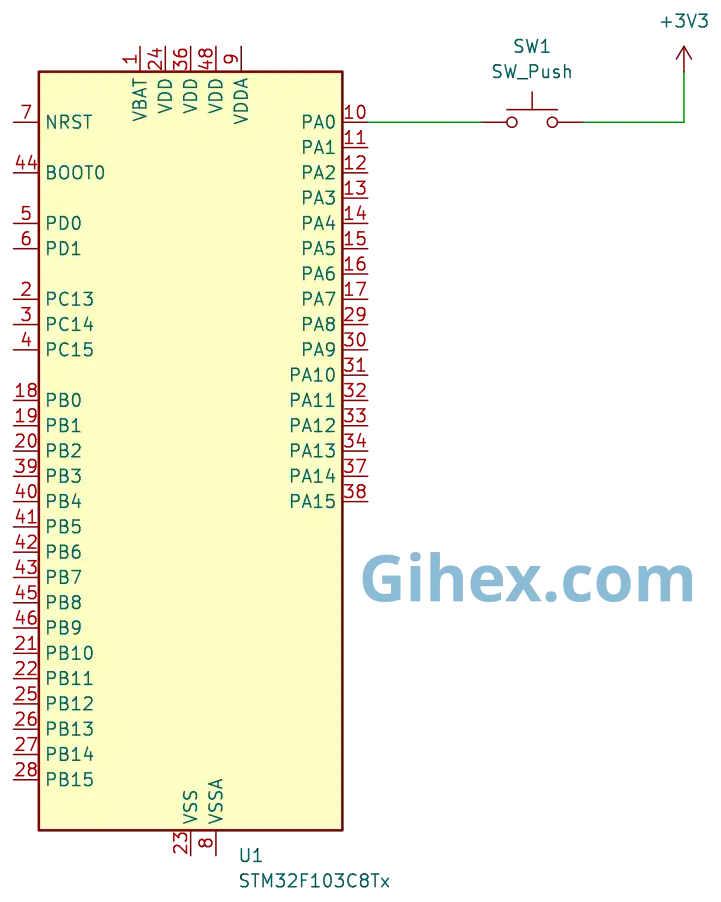
The schematic is the same as the one used in the previous article, please refer to that article for a more detailed explanation of the circuit.
Programming Interrupt on STM32F103C8 (Blue Pill) Timer as Input Capture with Rust
First, let’s create a new Rust project as explained in this article. Open the Cargo.toml file, then define a new binary executable named timer-interrupt :
1[[bin]]
2name = "timer-interrupt"
3path = "src/main.rs"
4test = false
5bench = false
Next, open the src/main.rs file and insert the following code:
Rust
 1#![no_std]
 2#![no_main]
 3
 4use core::sync::atomic::{AtomicU32, Ordering};
 5
 6use defmt_rtt as _;
 7use panic_probe as _;
 8
 9use cortex_m_rt::entry;
10use stm32f1xx_hal::{
11    flash::FlashExt,
12    pac::{self, interrupt},
13    prelude::*,
14    rcc::{Config, RccExt},
15    time::Hertz,
16    timer::{Event, Timer},
17};
As usual, we instruct the Rust compiler not to use the standard library and to ensure the program does not run on top of an operating system.
We also define the libraries that will be used in the project:
- The
atomiclibrary is used to define global variables so they can be accessed from both the main loop block and the interrupt function. - The
cortex_m_rtlibrary/crate is used to define the program’s entry point and handle the startup process. defmt_rttis used to send logging data to a PC or laptop via the Real-Time Transfer (RTT) protocol.- The
stm32f1xx_hallibrary allows us to access the STM32F103C8 microcontroller’s peripherals safely. panic_probeis used to handle runtime errors and will automatically send error logs to the host PC or laptop.
Rust
1static NUMB_OVERFLOW: AtomicU32 = AtomicU32::new(0);Create a global variable named NUMB_OVERFLOW to store the number of times the timer overflows. Here, we use the AtomicU32 variable type so that it can be accessed from both the main loop block and the interrupt function block (Interrupt Service Routine/ISR).
In the main function, add the following code:
Rust
1defmt::println!("STM32F103C8 Timer Interrupt with Input Capture");Sending a message to the PC/laptop to indicate that the program is a timer with interrupts.
Rust
 1let dp = pac::Peripherals::take().unwrap();
 2
 3let mut flash = dp.FLASH.constrain();
 4
 5let rcc = dp.RCC.constrain();
 6
 7let clock_config = Config::default()
 8    .use_hse(Hertz::MHz(8))
 9    .sysclk(Hertz::MHz(72))
10    .hclk(Hertz::MHz(72))
11    .pclk1(Hertz::MHz(36));
12
13let mut clocks = rcc.freeze(clock_config, &mut flash.acr);
ust as in the previous article, we configure the clocks to use an 8 MHz external clock (HSE). We then set the System Clock to 72 MHz, the Advanced High-performance Bus (AHB) peripheral clock to 72 MHz, and the Advanced Peripheral Bus 1 (APB1) clock to 36 MHz. Consequently, the Timer 2 clock frequency will be 72 MHz.
Rust
1let mut gpioa = dp.GPIOA.split(&mut clocks);
2
3let channel_1 = gpioa.pa0.into_pull_down_input(&mut gpioa.crl);
Access the GPIOA peripheral and configure the PA0 pin as a pull-down input. In the next step, we will connect the PA0 pin to Channel 1 of Timer 2.
Rust
1let timer2 = Timer::new(dp.TIM2, &mut clocks);
2unsafe {
3        pac::NVIC::unmask(interrupt::TIM2);
4}
Access the Timer 2 peripheral and enable the Timer 2 interrupt within the NVIC (Nested Vectored Interrupt Controller).
Rust
1let mut counter = timer2.counter_hz();The Timer 2 counter is enabled to allow it to start counting increments based on the configured clock.
Rust
1counter.listen(Event::Update);Enable the Update Event interrupt for Timer 2 on the STM32F103C8.
Rust
1let timer_register = unsafe { &*pac::TIM2::ptr() };Directly accessing the Timer 2 register pointer of the STM32F103C8.
Rust
1timer_register.ccmr1_input().modify(|_, w| w.cc1s().ti1());Configure Channel 1 of Timer 2 as an input and map Timer 2 Channel 1 to the PA0 pin.
Rust
1timer_register
2    .ccmr1_input()
3    .modify(|_, w| w.ic1f().fck_int_n8());
Enable the digital filter for Timer 2 Channel 1 to reduce debouncing effects.
Rust
1timer_register.ccer().modify(|_, w| w.cc1e().set_bit());Enable the Input Capture on Timer 2 Channel 1.
Rust
1 timer_register.ccer().modify(|_, w| w.cc1p().clear_bit());Configure Timer 2 Channel 1 to detect the Rising Edge.
Rust
1 counter.start_raw(7199, 65535);Run Timer 2 with a prescaler of 7199 and an Auto-Reload register value of 65535.
Rust
1let mut start_press_tick = 0u16;
2
3let mut is_pressed = false;
Create variables to store the tick value when the push button is first pressed and to store the current status of the push button.
Rust
1loop {
2    if counter.get_interrupt().contains(Event::C1) {
3        // Capture channel 1 interupt
4    }
5}
Inside the loop block, we check for a capture/compare event on channel 1. If a capture/compare event occurs on channel 1, the CPU will execute the code below. Unlike the previous article, where we directly read the CC1IF bit of the TIM2_SR register, in this tutorial, we utilize the get_interrupt method provided by the stm32f1xx_hal crate. Both methods serve the same purpose.
If a capture/compare event occurs on Channel 1, the following program will be executed:
Rust
 1let captured_tick = timer_register.ccr1().read().ccr().bits() as u16;
 2
 3let pin_is_high = channel_1.is_high();
 4
 5if pin_is_high && !is_pressed {
 6    start_press_tick = captured_tick;
 7    NUMB_OVERFLOW.store(0, Ordering::SeqCst);
 8    timer_register.ccer().modify(|_, w| w.cc1p().set_bit());
 9
10    is_pressed = true;
11    defmt::println!("--- Button Pressed ---");
12    defmt::println!("start: {}", start_press_tick);
13} else if !pin_is_high && is_pressed {
14    // ELSE
15}
16
17counter.clear_interrupt(Event::C1);
If a capture/compare event occurs, retrieve the value from the Timer 2 Capture/Compare register. Next, check the status of the PA0 pin. If the PA0 pin is HIGH and the is_pressed variable is false (indicating a Rising edge), update the start_press_tick variable with the captured tick value. Then, reset the NUMB_OVERFLOW global variable to 0, configure channel 1 to detect a Falling edge, and set the is_pressed variable to true. Finally, do not forget to clear the channel 1 capture/compare interrupt flag, even though it is typically cleared automatically.
When the channel 1 capture/compare detects a Falling edge, the following program will be executed:
Rust
 1timer_register.ccer().modify(|_, w| w.cc1p().clear_bit());
 2
 3let total_overflow = NUMB_OVERFLOW.load(Ordering::SeqCst);
 4
 5let total_tick =
 6    (total_overflow * 65536) + captured_tick as u32 - start_press_tick as u32;
 7
 8defmt::println!(
 9    "end: {} | total_overflow: {}",
10    captured_tick,
11    total_overflow
12);
13defmt::println!("press long: {} ms", total_tick as f32 / 10f32);
14defmt::println!("----------------------");
15is_pressed = false;
If the PA0 pin is LOW and the is_pressed variable is true (indicating a Falling edge), we will calculate the total ticks elapsed while the push button was pressed. Next, use the total ticks to calculate the duration of the button press and set the is_pressed variable to false. At this point, we also reconfigure the channel 1 input capture mode back to rising edge.
Furthermore, do not forget to create the function (Interrupt Service Routines/ISR) that the CPU will execute when a Timer 2 interrupt occurs; the following is the interrupt function that we will use.
Rust
 1
 2#[interrupt]
 3fn TIM2() {
 4    let timer_register = unsafe { &*pac::TIM2::ptr() };
 5
 6    // check update interrupt flag
 7    if timer_register.sr().read().uif().bit_is_set() {
 8        // Increment overflow count
 9        NUMB_OVERFLOW.fetch_add(1, Ordering::SeqCst);
10        // Clear update interrupt flag
11        timer_register.sr().modify(|_, w| w.uif().clear_bit());
12    }
13}
Create an interrupt function (ISR) for Timer 2. Inside this function, we check the update interrupt flag. If the interrupt was triggered by an update event, we increment the NUMB_OVERFLOW global variable by 1, and subsequently clear the update interrupt flag bit.
  1#![no_std]
  2#![no_main]
  3
  4use core::sync::atomic::{AtomicU32, Ordering};
  5
  6use defmt_rtt as _;
  7use panic_probe as _;
  8
  9use cortex_m_rt::entry;
 10use stm32f1xx_hal::{
 11    flash::FlashExt,
 12    pac::{self, interrupt},
 13    prelude::*,
 14    rcc::{Config, RccExt},
 15    time::Hertz,
 16    timer::{Event, Timer},
 17};
 18
 19static NUMB_OVERFLOW: AtomicU32 = AtomicU32::new(0);
 20
 21#[entry]
 22fn main() -> ! {
 23    defmt::println!("STM32F103C8 Timer Interrupt with Input Capture");
 24
 25    let dp = pac::Peripherals::take().unwrap();
 26
 27    let mut flash = dp.FLASH.constrain();
 28
 29    let rcc = dp.RCC.constrain();
 30
 31    let clock_config = Config::default()
 32        .use_hse(Hertz::MHz(8))
 33        .sysclk(Hertz::MHz(72))
 34        .hclk(Hertz::MHz(72))
 35        .pclk1(Hertz::MHz(36));
 36
 37    let mut clocks = rcc.freeze(clock_config, &mut flash.acr);
 38
 39    let mut gpioa = dp.GPIOA.split(&mut clocks);
 40
 41    let channel_1 = gpioa.pa0.into_pull_down_input(&mut gpioa.crl);
 42
 43    let timer2 = Timer::new(dp.TIM2, &mut clocks);
 44
 45    // enable listen update overflow
 46    // timer_register.dier.modify(|_, w| w.uie().set_bit());
 47
 48    unsafe {
 49        pac::NVIC::unmask(interrupt::TIM2);
 50    }
 51
 52    let mut counter = timer2.counter_hz();
 53
 54    counter.listen(Event::Update);
 55
 56    let timer_register = unsafe { &*pac::TIM2::ptr() };
 57
 58    // 00 output
 59    // 01 input
 60    // 10 Input, (Cross-mapping channel 2).
 61    timer_register.ccmr1_input().modify(|_, w| w.cc1s().ti1());
 62
 63    timer_register
 64        .ccmr1_input()
 65        .modify(|_, w| w.ic1f().fck_int_n8());
 66
 67    timer_register.ccer().modify(|_, w| w.cc1e().set_bit());
 68
 69    timer_register.ccer().modify(|_, w| w.cc1p().clear_bit());
 70
 71    counter.start_raw(7199, 65535);
 72
 73    let mut start_press_tick = 0u16;
 74
 75    let mut is_pressed = false;
 76
 77    loop {
 78        if counter.get_interrupt().contains(Event::C1) {
 79            let captured_tick = timer_register.ccr1().read().ccr().bits() as u16;
 80
 81            let pin_is_high = channel_1.is_high();
 82
 83            if pin_is_high && !is_pressed {
 84                start_press_tick = captured_tick;
 85                NUMB_OVERFLOW.store(0, Ordering::SeqCst);
 86                timer_register.ccer().modify(|_, w| w.cc1p().set_bit());
 87
 88                is_pressed = true;
 89                defmt::println!("--- Button Pressed ---");
 90                defmt::println!("start: {}", start_press_tick);
 91            } else if !pin_is_high && is_pressed {
 92                timer_register.ccer().modify(|_, w| w.cc1p().clear_bit());
 93
 94                let total_overflow = NUMB_OVERFLOW.load(Ordering::SeqCst);
 95
 96                let total_tick =
 97                    (total_overflow * 65536) + captured_tick as u32 - start_press_tick as u32;
 98
 99                defmt::println!(
100                    "end: {} | total_overflow: {}",
101                    captured_tick,
102                    total_overflow
103                );
104                defmt::println!("press long: {} ms", total_tick as f32 / 10f32);
105                defmt::println!("----------------------");
106                is_pressed = false;
107            }
108
109            counter.clear_interrupt(Event::C1);
110        }
111    }
112}
113
114#[interrupt]
115fn TIM2() {
116    let timer_register = unsafe { &*pac::TIM2::ptr() };
117
118    // check update interrupt flag (overflow)
119    if timer_register.sr().read().uif().bit_is_set() {
120        // Increment overflow count setiap kali timer melewati 65535
121        NUMB_OVERFLOW.fetch_add(1, Ordering::SeqCst);
122        // Clear update interrupt flag
123        timer_register.sr().modify(|_, w| w.uif().clear_bit());
124    }
125}
Connect the Blue Pill board (STM32F103C8 microcontroller) to your PC/laptop using an ST-Link USB Downloader and Debugger, as explained in this article. After that, execute the program by running the command cargo run --bin timer-interrupt in the VSCode terminal. The following is the output when the program is executed.
Source Code
The source code used in this article can be accessed at the GitHub repository.
If you encounter any difficulties while following this tutorial, do not hesitate to contact us through the contact page.