Toggling STM32 GPIO Status Using Timer Output Compare
In the previous article, we discussed input capture, in this article we will discuss output compare. Output compare is the opposite of input capture. While in input capture, the counter register value (TIMx_CNT) is copied into the capture/compare register (TIMx_CCRx) when a voltage transition occurs on the pin connected to the Timer channel, in output compare, the pin status (High/Low) is modified when the counter register value (TIMx_CNT) matches the capture/compare register value (TIMx_CCRx).
Output Compare on STM32 Timer
Output compare is an STM32 Timer feature used to change the status of the pin connected to the Timer channel. The pin status changes when the counter register value (TIMx_CNT) matches the capture/compare register value (TIMx_CCRx).
By using output compare, we can accurately change the GPIO pin status at specific periods without involving the CPU, thereby saving CPU resources.
There are several output compare modes that can be configured through the capture/compare mode register (CCMR1) via the 3-bit output compare mode (OCxM) field. The following are the types of output compare modes on the STM32 Timer:
Toggle Mode (
OCxM=0b011)Whenever the counter register value matches the capture compare register value (
CNT=CCR1), the pin status will be toggled. If it is initially HIGH, it becomes LOW. If it is initially LOW, it becomes HIGH.An example of its usage is to make an LED blink at precise, specific intervals.
PWM Mode 1 (
OCxM=0b110)The channel pin will remain HIGH as long as the counter register value is less than the capture compare register value (
CNT<CCR), and will become LOW when the counter register value is greater than or equal to the capture compare register value (CNT>=CCR).It is used for the precise control of light intensity or motor speed.
PWM Mode 2 (
OCxM=0b111)The channel pin will remain LOW as long as the counter register value is less than the capture compare register value (
CNT<CCR), and will become HIGH when the counter register value is greater than or equal to the capture compare register value (CNT>=CCR).It is used for the precise control of light intensity or the speed of active-LOW motors.
Frozen (
OCxM=0b000)The comparison between
CNTandCCR1does not change the channel pin status. It is used to trigger interrupts without modifying the status of the channel pin.Active on Match (
OCxM=0b001) dan Inactive on Match (OCxM=0b010)Active: The channel pin becomes HIGH immediately when the counter register value matches the capture compare register value (
CNT=CCR1). After that, the pin status will not change even if the counter register value matches the capture compare register value again.Inactive: The channel pin becomes LOW immediately when the counter register value matches the capture compare register value (
CNT=CCR1). After that, the pin status will not change even if the counter register value matches the capture compare register value again.Force Active (
OCxM=0b101) dan Force Inactive (OCxM=0b100)Force the pin to become HIGH or LOW instantly, regardless of the counter value.
Hardware Preparation
The following are the components used in this tutorial:
STM32F103C8 (Blue Pill)
The STM32F103C8 (Blue Pill) microcontroller is one of the variants of the STM32 microcontroller series. We will program this microcontroller using the Rust programming language to access the output compare features.
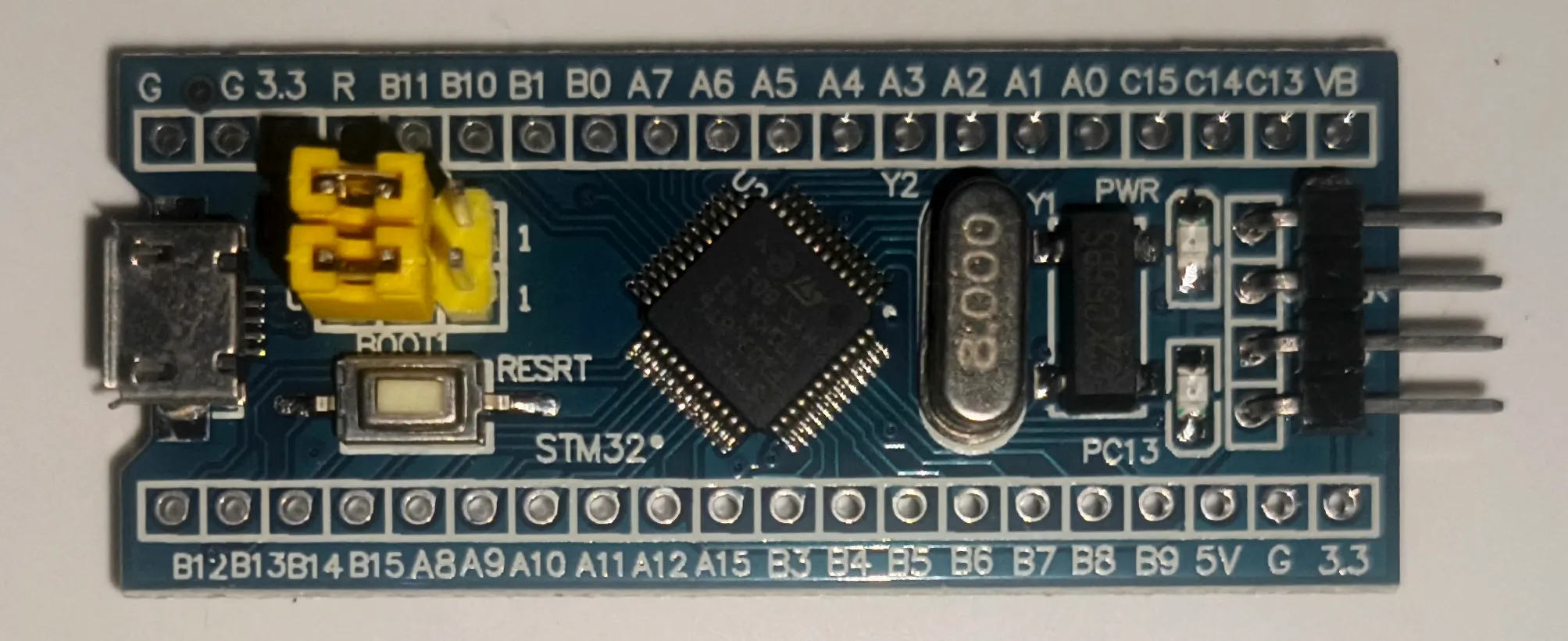
Minimum System Board STM32F103C8T6 (Blue Pill) ST-LINK USB Downloader Debuger
The ST-LINK USB Downloader/Debugger functions as a bridge between the PC or laptop and the STM32F103C8, allowing us to program the STM32F103C8 directly from the computer.
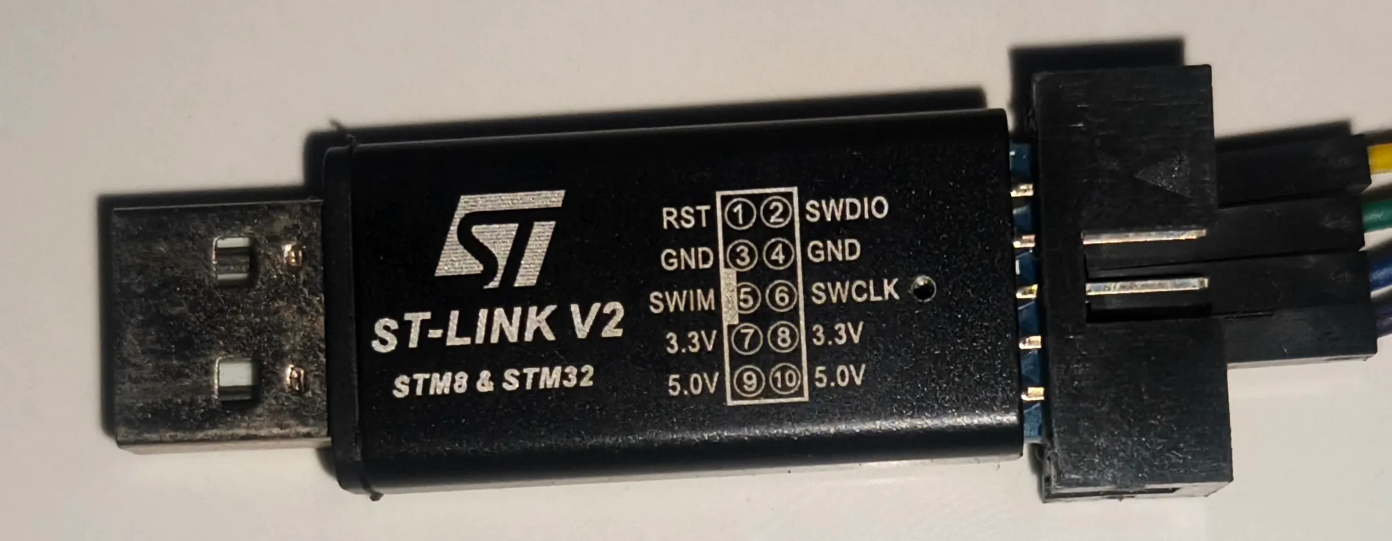
ST-Link USB Downloader/Debugger for programming the Blue Pill board Breadboard
A Breadboard (Project Board) is used to create electronic circuit prototypes without the need for soldering.
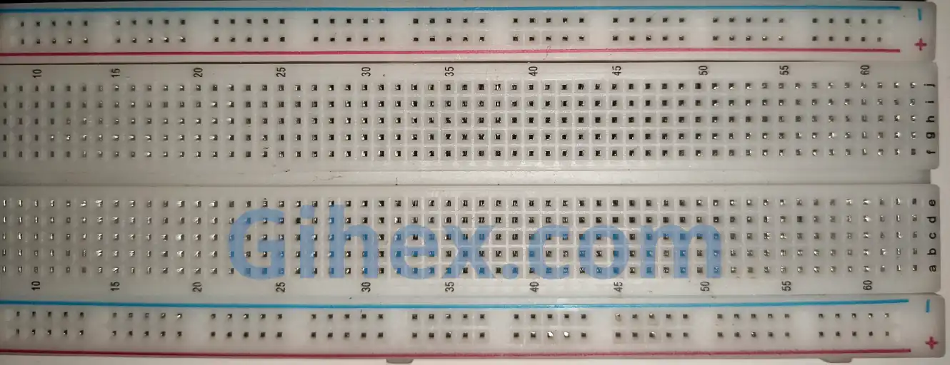
Breadboard (Project Board) Light Emitting Diode (LED)
LED is a type of diode that emits light when a forward bias voltage is applied. In this tutorial, we are using two 3mm LEDs: white and blue.
Resistor
Resistors are used as protection for LEDs against excessive electrical current. We are using 0.5-Watt resistors with a resistance value of 220 Ohms.
Jumper female to female
Female-to-female jumper wires are used to connect the Blue Pill to the ST-LINK USB Downloader/Debugger. Meanwhile, male-to-male jumper wires are used to build the circuit on the breadboard.
Using Output Compare on STM32 Blue Pill with Rust Programming Language
In this tutorial, we will program the STM32F103C8 to blink LEDs every 2 seconds using the Output Compare feature of Timer 2, Channel 1 and Channel 2, without remapping. The white LED is connected to pin PA0, and the blue LED is connected to pin PA1. We will configure both LEDs to toggle alternately every 2 seconds.
Schematic Circuit for Output Compare
Using the components listed above, please assemble the circuit on the breadboard according to the following schematic diagram:
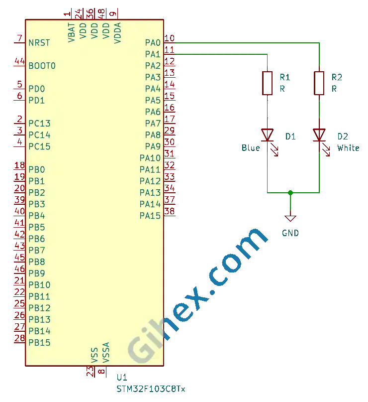
In this schematic, when pin PA0 is HIGH, the white LED will turn on, and when pin PA0 is LOW, the white LED will turn off. Similarly, when pin PA1 is HIGH, the blue LED will turn on, and when pin PA1 is LOW, the blue LED will turn off.
Programming STM32 Timers as Output Compare with Rust
First, we will create a Rust project for embedded systems as explained in this article. Open the Cargo.toml file, then add the following code to define a new binary executable named 'timer-output-compare' :
Toml
1[[bin]]
2name = "timer-output-compare"
3path = "src/main.rs"
4test = false
5bench = falseThe Gihex website relies on revenue from Smartlink/Directlink advertisements for its operational costs. To display the complete code for “Cargo.toml”, simply click the following Smartlink/Directlink button:
UnlockOpen the src/main.rs file and insert the following code:
Rust
 1#![no_std]
 2#![no_main]
 3
 4use defmt_rtt as _;
 5use panic_probe as _;
 6
 7use cortex_m_rt::entry;
 8use stm32f1xx_hal::{
 9    flash::FlashExt,
10    pac::{self},
11    prelude::*,
12    rcc::{Config, RccExt},
13    time::Hertz,
14    timer::Timer,
15};
Configure the Rust toolchain to avoid using the standard library so that the program can run in a bare-metal environment without an operating system.
Define all the libraries to be used:
- The
cortex_m_rtcrate/library: Used to define the program’s entry point and handle the startup process. defmt_rtt: Functions to send logging data to a PC/laptop using the Real-Time Transfer (RTT) protocol.- The
stm32f1xx_hallibrary: Enables safe access to the STM32F103C8 microcontroller peripherals. panic_probe: Used to handle runtime errors by automatically sending error logs to the host PC/laptop.
Inside the main function, fill it with the following code:
Rust
1defmt::println!("STM32F103C8 Timer Ouput Compare");Send a message to the PC/laptop terminal to mark it as the output compare program.
Rust
1let dp = pac::Peripherals::take().unwrap();Accessing the STM32F103C8 microcontroller device peripherals.
Rust
 1let mut flash = dp.FLASH.constrain();
 2
 3let rcc = dp.RCC.constrain();
 4
 5let clock_config = Config::default()
 6    .use_hse(Hertz::MHz(8))
 7    .sysclk(Hertz::MHz(72))
 8    .hclk(Hertz::MHz(72))
 9    .pclk1(Hertz::MHz(36));
10
11let mut clocks = rcc.freeze(clock_config, &mut flash.acr);
Configure the clock by using an 8 MHz external clock ( use_hse ), then set the system clock ( sysclk ) to 72 MHz, the Advanced High-Performance Bus clock ( hclk ) to 72 MHz, and Peripheral Clock 1 ( pclk1 ) to 36 MHz. Since the Peripheral 1 prescaler is greater than 1
, the clock frequency for Timer 2 is
.
Rust
1let mut gpioa = dp.GPIOA.split(&mut clocks);
2
3let _channel_1 = gpioa.pa0.into_alternate_push_pull(&mut gpioa.crl);
4let _channel_2 = gpioa.pa1.into_alternate_push_pull(&mut gpioa.crl);
Accessing the GPIO Port A peripherals and configuring pins PA0 and PA1 as alternate function push-pull outputs.
Rust
1let timer2 = Timer::new(dp.TIM2, &mut clocks);
2
3let mut counter = timer2.counter_hz();
Accessing the Timer 2 (TIM2) peripheral and configuring the timer as a counter.
Rust
1let timer2_register = unsafe { &*pac::TIM2::ptr() };Accessing the Timer 2 register pointer.
Rust
1// OC1M = 0b011 (Toggle mode for Channel)
2timer2_register
3    .ccmr1_output()
4    .modify(|_, w| unsafe { w.oc1m().bits(0b011) });
5timer2_register
6    .ccmr1_output()
7    .modify(|_, w| unsafe { w.oc2m().bits(0b011) });
Setting Output Compare Channel 1 and Channel 2 to Toggle mode.
Rust
1// enable capture/compare
2timer2_register.ccer().modify(|_, w| w.cc1e().set_bit());
3timer2_register.ccer().modify(|_, w| w.cc2e().set_bit());
Enabling Capture/Compare Channel 1 and Channel 2.
Rust
1// set polarity output
2// PA0 will be HIGH at first toggle
3timer2_register.ccer().modify(|_, w| w.cc1p().clear_bit());
4// PA1 will be LOW saat first toggle
5timer2_register.ccer().modify(|_, w| w.cc2p().set_bit());
Set the polarity for the Timer 2 Capture/Compare channels, so that Channel 1 is HIGH during the first toggle, while Channel 2 is LOW during the first toggle.
Rust
1// mengeset ccr ke 0
2timer2_register.ccr1().write(|w| unsafe { w.bits(0) });
3timer2_register.ccr2().write(|w| unsafe { w.bits(0) });
Set the Capture/Compare Channel 1 and Channel 2 values to 0. Thus, when the counter register value reaches 0, the logic states of pins PA0 and PA1 will be toggled.
Rust
1// Reset counter register start from 0 (optional)
2timer2_register.cnt().write(|w| unsafe { w.cnt().bits(0) });
Setting the counter register value to 0.
Rust
1counter.start_raw(7199, 20000);Running the counter with a prescaler of 7199 and an auto-reload register value of 20, 000.
Rust
1loop {
2    cortex_m::asm::nop();
3}
Inside the loop block, the CPU does not perform any operations.
The Gihex website relies on revenue from Smartlink/Directlink advertisements for its operational costs. To display the complete code for “src/main.rs”, simply click the following Smartlink/Directlink button:
UnlockRun the program by executing the command ‘cargo run --bin timer-output-compare’ in the terminal within the project folder.
Source Code
The source code used in this article can be accessed at this 🔒GitHub repository .
If you encounter any difficulties following this tutorial, please do not hesitate to contact us through the contact page.