Programming Blue Pill (STM32F103C8) Timers with Rust
In previous articles, we discussed using the STM32F103C8 microcontroller ADC, starting from the introduction and moving through various conversion (single, continuous, scan, and discontinuous) along with example programs in Rust. Now, we will discuss the Timer peripherals on the STM32F103C8 (STM32 Blue Pill).
We have actually utilized Timers in earlier articles to create delays . The STM32F103C8 features several types of timers: Advanced-control, General Purpose, System, and Watchdog. Each type has its own specific resolution and function. Previously, we generated delays by using the System Timer as a counter.
Introduction to Blue Pill (STM32F103C8) Timer Peripherals
Below is an explanation of the Timer peripheral types on the STM32F103C8 microcontroller:
- Advanced-control Timer: A 16-bit resolution
timerlocated on the APB2 bus with a maximum frequency of 72 MHz. The STM32F103C8 features one advanced-control timer, TIM1, equipped with 4 standard channels, 3 complementary output channels, and 1 break input channel. It can function as a counter, input capture, PWM (Pulse Width Modulation), one-pulse output, and output compare. Its advantages over general-purpose timers include the ability to generate programmable dead-time for complementary outputs, a break input feature, and higher accuracy. - General Purpose Timer: These have a 16-bit resolution and are located on the APB1 bus with a maximum frequency of 72 MHz. They are typically used for counting, input capture, PWM, one-pulse output, and output compare. The STM32F103C8 has three general purpose timers: TIM2, TIM3, and TIM4, each featuring 4 channels.
- System Timer: A 24-bit resolution timer integrated into the Cortex-M3 CPU. It does not have external channels and is commonly used to create delays, as demonstrated in our previous articles.
- Watchdog: Designed to reset the STM32F103C8 microcontroller if a “hang” occurs. Under normal conditions, the watchdog counter is constantly reset. However, if the CPU encounters an error or freezes, the counter will reach a predefined value, triggering an automatic system reset. The STM32F103C8 includes two watchdogs: WWDG (Window Watchdog) and IWDG (Independent Watchdog).
In general, the functions of a Timer are as follows:
- Counter: The timer counts every tick (in internal clock mode) or every time a channel receives a voltage transition (in external clock mode) up to a specified maximum value. Counter modes include upcounting, downcounting, and center-aligned mode (up/down counting).
- Input Capture: The timer counts at the timer frequency (counter ticks); if a voltage transition occurs on a channel, the current counter value is stored. Input capture modes include Basic Input Capture, PWM (Pulse Width Modulation) Input, input capture with slave mode controller, and input capture with prescaler. This function is used to measure pulse width.
- Output Compare: The timer counts according to the timer frequency and changes the output channel state when the counter value reaches a specific threshold. Output compare modes include frozen, active on match, inactive on match, toggle on match, and PWM.
- PWM (Pulse Width Modulation): A specific mode of output compare. In this mode, the output pulse width of the channel can be adjusted as defined. The STM32F103C8 features two PWM modes (PWM Mode 1 and PWM Mode 2) with two alignment types: edge alignment and center alignment. This is used to control LED brightness and motor speed.
- One-Pulse Mode: The channel outputs a single pulse when the counter value reaches a specific threshold, after which the timer stops.
- Complementary Output: Exclusive to Advanced-control Timers (TIM1). When enabled, the complementary channel maintains the opposite state of the normal channel. If the normal channel is HIGH, the complementary channel will be LOW, and vice versa.
Timer 1 (TIM1) on the Blue Pill (STM32F103C8)
Timer 1 (TIM1) is the advanced-control timer on the STM32F103C8, featuring a 16-bit resolution (0–65535) and a maximum frequency of 72 MHz. Timer 1 offers higher accuracy compared to general-purpose timers. In addition to standard and complementary channels, Timer 1 is equipped with a Break Input channel designed to receive external triggers. When the Break Input channel is triggered, all PWM outputs on the channels are immediately halted (reset). Below are the Timer 1 channels for the STM32F103C8, along with their corresponding pins and available remaps:
| Channel | Default Pin | Partial Remap | Full Remap |
|---|---|---|---|
| TIM1_CH1 | PA8 | - | - |
| TIM1_CH2 | PA9 | - | - |
| TIM1_CH3 | PA10 | - | - |
| TIM1_CH4 | PA11 | - | - |
| TIM1_CH1N | PB13 | PA7 | - |
| TIM1_CH2N | PB14 | PB0 | - |
| TIM1_CH3N | PB15 | PB1 | - |
| TIM1_BKIN | PB12 | PA6 | - |
Pro Tip: If the default channel pins are already allocated for other purposes, you can utilize the Remap feature to reroute the Timer channels to alternative pins, as specified in the table.
Timer 2 (TIM2) on the Blue Pill (STM32F103C8)
Timer 2 (TIM2) is a general-purpose timer on the STM32F103C8 with a 16-bit resolution (0–65535). Its maximum frequency is 72 MHz. When the APB1 prescaler is greater than 1, the Timer 2 clock frequency is automatically multiplied by 2. Below are the Timer 2 channels for the STM32F103C8, along with their corresponding pins and available remaps:
| Channel | Default Pin | Partial Remap 1 | Partial Remap 2 | Full Remap |
|---|---|---|---|---|
| CH1 / ETR | PA0 | PA15 | - | PB15 |
| CH2 | PA1 | PB3 | - | PB3 |
| CH3 | PA2 | - | PB10 | PB10 |
| CH4 | PA3 | - | PB11 | PA11 |
Catatan: On the STM32F103C8
Timer, when usingChannel Remap, only one remap configuration can be selected at a time. Therefore, it is impossible to use full remap, partial remap 1, and partial remap 2 simultaneously.
Timer 3 (TIM3) on the Blue Pill (STM32F103C8)
Timer 3 (TIM3) is a general-purpose timer on the STM32F103C8 featuring a 16-bit resolution (0–65535) and a maximum frequency of 72 MHz. When the APB1 prescaler is greater than 1, the Timer 3 clock frequency is automatically doubled. Below are the Timer 3 channels for the STM32F103C8, along with their corresponding pins and available remaps:
| Channel | Default Pin | Partial Remap | Full Remap |
|---|---|---|---|
| CH1 | PA6 | PB4 | - |
| CH2 | PA7 | PB5 | - |
| CH3 | PB0 | - | - |
| CH4 | PB1 | - | - |
Timer 4 (TIM4) on the Blue Pill (STM32F103C8)
Timer 4 (TIM4) is a general-purpose timer on the STM32F103C8 with a 16-bit resolution (0–65535) and a maximum frequency of 72 MHz. When the APB1 prescaler is greater than 1, the Timer 4 clock frequency is automatically doubled. Below are the Timer 4 channels for the STM32F103C8:
| Channel | Default Pin | Partial Remap | Full Remap |
|---|---|---|---|
| CH1 | PB6 | - | - |
| CH2 | PB7 | - | - |
| CH3 | PB8 | - | - |
| CH4 | PB9 | - | - |
Hardware Preparation
In this tutorial, we will use several hardware components, including: the STM32F103C8 microcontroller (Blue Pill), an ST-Link USB Downloader/Debugger, a breadboard, a push button, and various jumper wires (female-to-female and male-to-male).
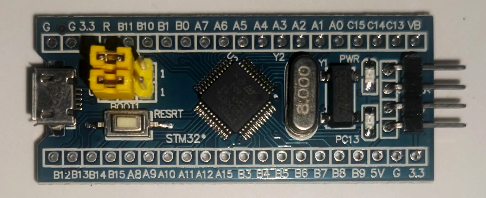
Microcontroller STM32F103C8 (Blue Pill)
This is the core component required, as we will be accessing the Timer peripherals of the STM32F103C8 microcontroller. We are using the Blue Pill, but you may also use other development boards that feature the STM32F103C8 chip.
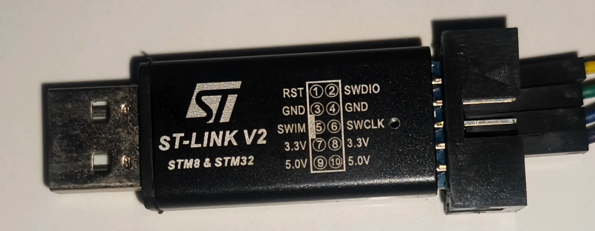
ST-LINK USB Downloader Debuger
The ST-LINK USB Downloader/Debugger serves to connect your PC or laptop to the STM32F103C8 microcontroller, enabling you to program and perform debugging on the STM32F103C8 directly from your computer.
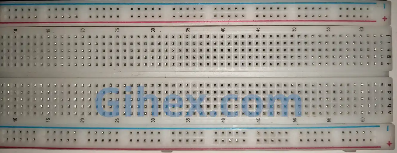
Breadboard
A breadboard is a component used to facilitate the creation of electronic circuit prototypes. By using a breadboard, there is no need to solder components, you can simply use male-to-male jumper wires.
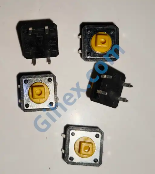
Push Button
A push button is a component that connects its two terminals when pressed. We will use the push button as an input for the STM32F103C8 microcontroller.
More detailed explanations regarding the functions of the components used can be found on the STM32F103C8 setup with Rust page.
Accessing Blue Pill (STM32F103C8) Timers with Rust
In this tutorial, we will use the Timer 2 (TIM2) peripheral of the STM32F103C8 microcontroller as a counter . Other Timer functions will be discussed in future articles.
Timer 2 has a 16-bit resolution, meaning the maximum counter value is 65535. Before using the counter, we must first determine the timer frequency to calculate the timer prescaler value. The following is the formula for determining the prescaler:
Key:
- : The frequency from the microcontroller’s main system to the Timer.
- : The specific Timer frequency that we define.
We must determine the appropriate
and
to ensure they do not exceed the capacity. The prescaler value is stored in the TIMx_PSC (Prescaler) register. In the STM32 RM0008 datasheet, within the counter timing diagram section, the term CLK_PSC is equivalent to
.
As explained above, there are three Timer modes for use as a counter:
- Upcounting: The timer will count from 0 up to a specified maximum value repeatedly. In this mode, the value of the
TIMx_CNT(Counter register) starts at 0 and increments by 1 until it reaches the definedTIMx_ARR(Auto-reload register) value. Once theTIMx_CNTvalue exceeds theTIMx_ARR(TIMx_ARR+1), theTIMx_CNTregister is reset to 0. - Downcounting: The timer will count from a specified maximum value down to 0 repeatedly. In this mode, the
TIMx_CNTvalue starts at theTIMx_ARRvalue and decrements by 1 until it reaches 0. Once theTIMx_CNTregister reaches 0, it is reset back to theTIMx_ARRvalue. - Center-aligned mode (Up/Down counting): The timer will first count from 0 up to a specified maximum value, then count back down to 0, repeating this cycle indefinitely. In this mode, the
TIMx_CNTvalue starts at 0 and increments by 1 until it reaches the definedTIMx_ARRvalue. Once theTIMx_CNTvalue exceeds theTIMx_ARR(TIMx_ARR+1), the timer switches to downcounting until theTIMx_CNTregister reaches 0.
There are two clock sources used to change the value of the TIMx_CNT (Counter register) when the Timer is functioning as a counter:
Internal Clock: In this type, the timer counts ticks from the timer’s internal frequency. For every 1 tick, the
TIMx_CNT(Counter register) value changes by 1 according to its mode. This is typically used to create both blocking and non-blocking delays. Since it uses an internal clock, the timer does not utilize external channels.External Clock: In this type, the timer counts based on voltage changes on a specified channel. Every time a voltage level transition occurs on the channel, the
TIMx_CNTregister value changes by 1 according to its mode. This is used to count the number of occurrences of an external event.
STM32F103C8 Timer as Counter with Clock Internal Using Rust
In this tutorial, we will create an upcounting counter by utilizing the Timer 2 peripheral. We will check the value of the TIMx_CNT register every 1 second. We will make use of the methods provided by the stm32f1xx_hal crate.
First, let’s create a new Rust project according to this page. Open the Cargo.toml file and insert the following code to define a new binary executable:
1[[bin]]
2name = "timer-counter-internal"
3path = "src/main.rs"
4test = false
5bench = false
Next, open the src/main.rs file and add the following code to inform the compiler that this program does not use the standard library and does not run on an operating system:
1#![no_std]
2#![no_main]
Defining all the libraries used:
Rust
 1use defmt_rtt as _;
 2use panic_probe as _;
 3
 4use cortex_m_rt::entry;
 5use stm32f1xx_hal::{
 6    flash::FlashExt,
 7    pac,
 8    prelude::*,
 9    rcc::{Config, RccExt},
10    time::Hertz,
11};
The cortex-m-rt library/crate is used to define the entry point of the program and handle the startup process. defmt_rtt serves to transmit data to the PC/laptop for logging using the Real-Time Transfer (RTT) protocol. The stm32f1xx_hal library allows us to access the STM32F103C8 microcontroller peripherals safely. panic_probe is used to handle runtime errors and will automatically send error logs to the host PC/laptop.
In the main function, add the following code so that we can access the STM32F103C8 peripherals:
Rust
1defmt::println!("STM32F103C8 Timer as Counter");
2
3let dp = pac::Peripherals::take().unwrap();
Send a message to the PC/laptop terminal to mark the program as a counter. Then, access the STM32F103C8 peripherals.
Rust
 1let mut flash = dp.FLASH.constrain();
 2let rcc = dp.RCC.constrain();
 3
 4let clock_config = Config::default()
 5    .use_hse(Hertz::MHz(8))
 6    .sysclk(Hertz::MHz(72))
 7    .hclk(Hertz::MHz(36))
 8    .pclk1(Hertz::MHz(36));
 9
10let mut clocks = rcc.freeze(clock_config, &mut flash.acr);
Access the Flash and Reset & Clock Control (RCC) peripherals. Configure the system clocks using an 8 MHz High-Speed External Clock ( use_hse ), setting the System Clock ( sysclk ) to 72 MHz, the Advanced High-performance Bus ( hclk ) to 36 MHz, and the Peripheral Bus 1/APB1 ( pclk1 ) to 36 MHz. Finally, apply the clock configuration using the freeze method.
Rust
1let mut counter = dp.TIM2.counter::<1_000>(&mut clocks);Access the Timer 2 peripheral and set its frequency to 1 kHz (1000 ticks per second). The counter method will automatically calculate the required prescaler. Since Timer 2 has a 16-bit resolution, the maximum prescaler value is 65535.
Warning: To prevent program errors caused by the prescaler exceeding its capacity (65535), we must determine the appropriate timer frequency and clock frequency.
In this case, we use
hclk=36 MHzandpclk1=36 MHz, resulting in a timer clock frequency of 36 MHz:Consequently, the timer prescaler is 35999, which is still within the safe capacity limit.
In a scenario where
hclk=72 MHzandpclk1=36MHz are used, the timer clock frequency becomes 72 MHz. As mentioned above, because the APB1 prescaler is greater than 1, the timer clock frequency effectively becomes twice the pclk1 value:This results in a timer prescaler of 71999, which causes an error because the value exceeds the register capacity (65535).
Rust
1counter.start(3000.millis()).unwrap();Start the counter with a 3000 ms timeout. This method also automatically sets the TIMx_ARR (Auto-Reload Register) value to the timeout ticks. Since we are using a timer frequency of 1 kHz (1000 ticks per second), reaching 3 seconds (3000 ms) requires 3000 ticks. Consequently, the TIMx_ARR register value will be set to
. This value is safe as it is well below the maximum limit (65535).
Pro Tip: To calculate the TIMx_ARR value from a specific timeout value, the following formula can be used:
or
In this case, we are using a timer frequency of 1 kHz (1000 Hz) and a timeout of 3000 ms (3 seconds), resulting in:
If we use a timeout of 80 seconds, then:
The TIMx_ARR value exceeds the maximum capacity (65535), which will result in a runtime error.
Rust
 1let mut last_update_time = counter.now();
 2
 3let interval = 1000.millis::<1, 1000>();
 4
 5loop {
 6    let now = counter.now();
 7
 8    if now.ticks().wrapping_sub(last_update_time.ticks()) >= interval.ticks() {
 9        defmt::println!("1000 ms passed | Current counter value: {}", now.ticks());
10        last_update_time = now;
11    }
12}
Create variables to store the last counter value and the interval for sending messages to the PC/laptop terminal. Here, we use a 1-second (1000 ms) interval. Our main program will run inside the loop block. First, retrieve the current counter value, then subtract it by the stored last counter value. If the result is greater than or equal to the interval, send a message to the PC/laptop terminal and update the last counter value with the current one. Using this method, we can create a non-blocking delay.
 1#![no_std]
 2#![no_main]
 3
 4use defmt_rtt as _;
 5use panic_probe as _;
 6
 7use cortex_m_rt::entry;
 8use stm32f1xx_hal::{
 9    flash::FlashExt,
10    pac,
11    prelude::*,
12    rcc::{Config, RccExt},
13    time::Hertz,
14};
15
16#[entry]
17fn main() -> ! {
18    defmt::println!("STM32F103C8 Timer as Counter");
19
20    let dp = pac::Peripherals::take().unwrap();
21
22    let mut flash = dp.FLASH.constrain();
23
24    let rcc = dp.RCC.constrain();
25
26    let clock_config = Config::default()
27        .use_hse(Hertz::MHz(8))
28        .sysclk(Hertz::MHz(72))
29        .hclk(Hertz::MHz(36))
30        .pclk1(Hertz::MHz(36));
31
32    let mut clocks = rcc.freeze(clock_config, &mut flash.acr);
33
34    let mut counter = dp.TIM2.counter::<1_000>(&mut clocks);
35
36    counter.start(3000.millis()).unwrap();
37
38    let mut last_update_time = counter.now();
39
40    let interval = 1000.millis::<1, 1000>();
41
42    loop {
43        let now = counter.now();
44
45        if now.ticks().wrapping_sub(last_update_time.ticks()) >= interval.ticks() {
46            defmt::println!("1000 ms passed | Current counter value: {}", now.ticks());
47            last_update_time = now;
48        }
49    }
50}
Run the program by entering the command ‘cargo run --bin timer-counter-internal’ in the VSCode terminal. The results are as follows:
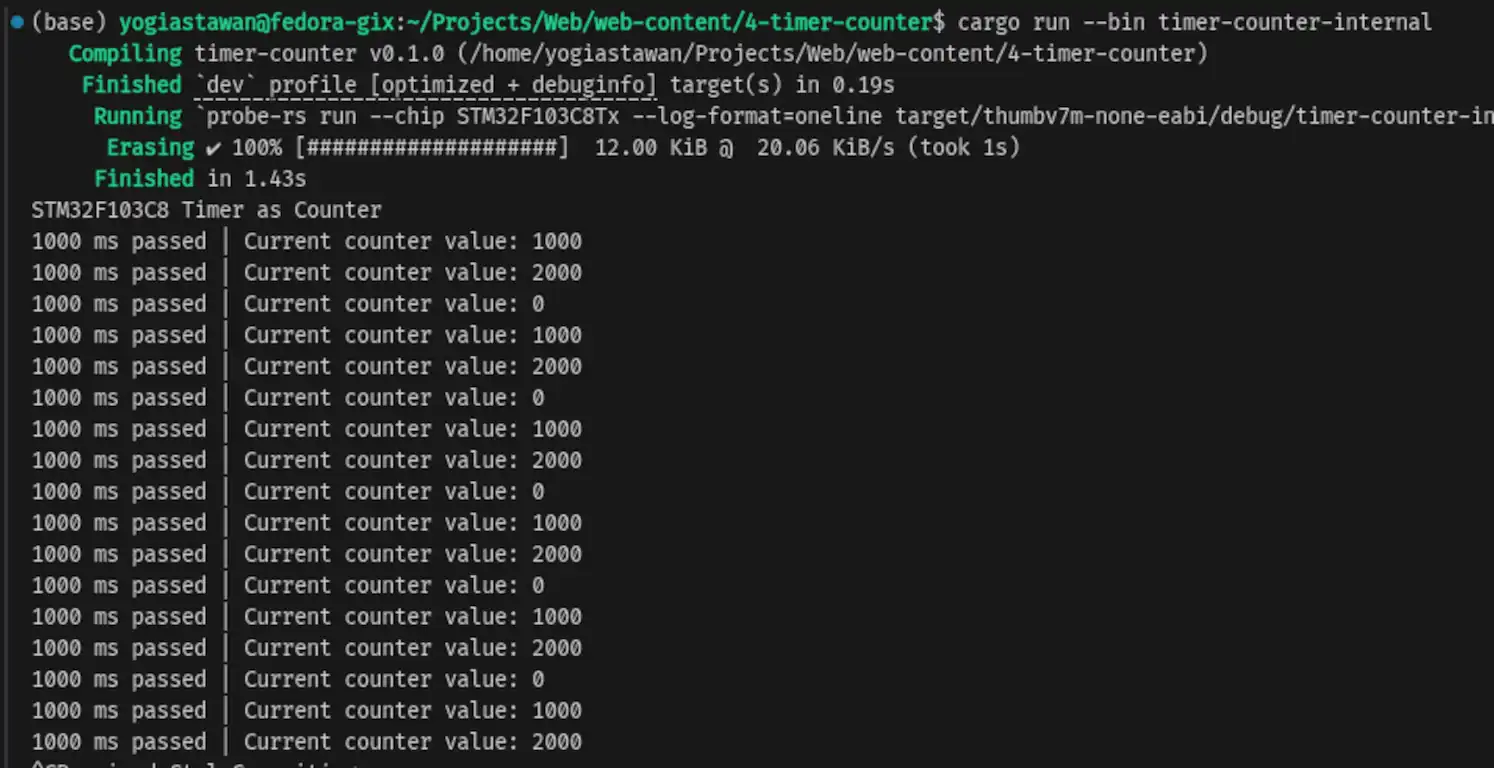
Timer 2 (TIM2) as counterIn these results, we can see that the microcontroller sends a message to the PC/laptop terminal every 1 second when the counter values reach 1000, 2000, and 0. This occurs because once the counter reaches the TIMx_ARR register value+1 (2999+1 = 3000), the counter value is automatically reset to 0.
STM32F103C8 Timer as Counter with Clock External Using Rust
In this tutorial, the timer will no longer use the internal clock. Instead, it will utilize an external clock which also serves as a trigger on the channel. This time, we will use the counter to track how many times a push button is pressed. We will use Timer 2 (TIM2) Channel 1 (Pin PA0). Channel 1 will be configured to detect a rising edge, so that whenever the voltage transitions from 0V to 3.3V, the counter value increments by 1. To achieve this, we need to configure pin PA0 as an input with a pull-down resistor connected to the push button. The push button will supply 3.3V to pin PA0 when pressed. Below is the schematic diagram of the push button and STM32F103C8 microcontroller circuit:
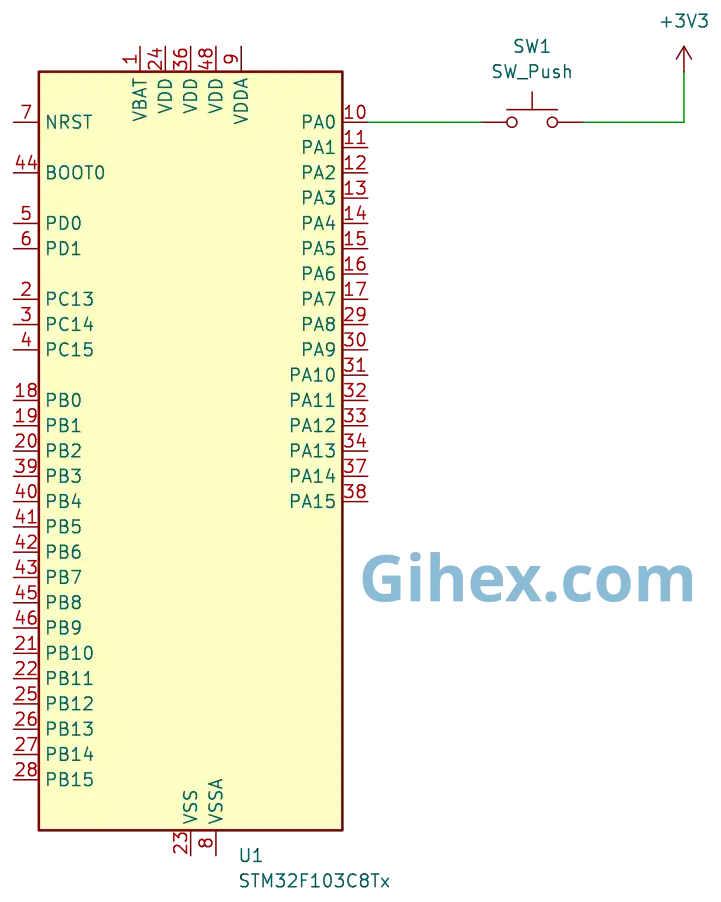
Since the stm32f1xx_hal crate does not provide a specific method for using an external clock, we will implement it by accessing the registers directly. Please build the circuit on your breadboard according to the schematic before proceeding to the programming section.
First, let’s define a new binary executable named timer-counter-external in the Rust project we created previously:
1[[bin]]
2name = "timer-counter-external"
3path = "src/counter_external.rs"
4test = false
5bench = false
Create the file src/counter_external.rs. Then, fill it with the following code to inform the compiler that we are not using the standard library and that the program is not running on an operating system, as well as to define all the libraries we will use:
 1#![no_std]
 2#![no_main]
 3
 4use defmt_rtt as _;
 5use panic_probe as _;
 6
 7use cortex_m_rt::entry;
 8use stm32f1xx_hal::{
 9    flash::FlashExt,
10    pac,
11    prelude::*,
12    rcc::{Config, RccExt},
13    time::Hertz,
14};
In the main function, add the following code to access the STM32F103C8 peripherals:
Rust
 1defmt::println!("STM32F103C8 Timer as Counter External");
 2
 3let dp = pac::Peripherals::take().unwrap();
 4
 5let mut flash = dp.FLASH.constrain();
 6
 7let rcc = dp.RCC.constrain();
 8
 9let clock_config = Config::default()
10    .use_hse(Hertz::MHz(8))
11    .sysclk(Hertz::MHz(72))
12    .hclk(Hertz::MHz(36))
13    .pclk1(Hertz::MHz(36));
14
15let mut clocks = rcc.freeze(clock_config, &mut flash.acr);
This is the same code as before for accessing the STM32F103C8 peripherals and configuring the clocks.
Rust
1let mut gpioa = dp.GPIOA.split(&mut clocks);
2let _pa0 = gpioa.pa0.into_pull_down_input(&mut gpioa.crl);
Configure pin PA0 (TIM2 Channel 1) as a pull-down input. This ensures that, by default, the pin is connected to GND (via an internal resistor). When the button is pressed, the system will detect a 3.3V signal (Rising Edge).
Rust
1let timer2 = dp.TIM2;
2
3unsafe {
4    let rcc_ptr = pac::RCC::ptr();
5    (*rcc_ptr).apb1enr().modify(|_, w| w.tim2en().set_bit());
6}
Access the Timer 2 peripherals and enable the clock for Timer 2.
Rust
1timer2
2    .ccmr1_input()
3    .modify(|_, w| unsafe { w.bits(0xF << 4) });
Enable the digital filter on Channel 1 to ensure stable readings.
Rust
1timer2
2    .ccer()
3    .modify(|_, w| w.cc1p().clear_bit().cc1e().set_bit());
By setting the cc1e register bit, Channel 1 is activated as a capture input. The cc1p register bit determines the capture polarity for Channel 1, when cc1p is set to 0, it detects a rising edge, and when set to 1, it detects a falling edge.
Rust
1timer2
2    .smcr()
3    .modify(|_, w| unsafe { w.sms().bits(0b111).ts().bits(0b101) });
Change the timer clock source to an external source, which simultaneously serves as the channel trigger. Additionally, configure the system to utilize the digital filter.
Rust
 1timer2.cr1().modify(|_, w| w.cen().set_bit());
 2
 3let mut last_count = 0;
 4
 5loop {
 6    let current_count = timer2.cnt().read().cnt().bits();
 7
 8    if current_count != last_count {
 9        defmt::println!("Counter value: {}", current_count);
10        last_count = current_count;
11    }
12
13}
Enable the timer by setting the cen bit to 1. Then, read the counter value from the cnt register. If the counter value is not equal to the previous value, send the value to the PC/laptop terminal.
 1#![no_std]
 2#![no_main]
 3
 4use defmt_rtt as _;
 5use panic_probe as _;
 6
 7use cortex_m_rt::entry;
 8use stm32f1xx_hal::{
 9    flash::FlashExt,
10    pac,
11    prelude::*,
12    rcc::{Config, RccExt},
13    time::Hertz,
14};
15
16#[entry]
17fn main() -> ! {
18    defmt::println!("STM32F103C8 Timer as Counter External");
19
20    let dp = pac::Peripherals::take().unwrap();
21
22    let mut flash = dp.FLASH.constrain();
23
24    let rcc = dp.RCC.constrain();
25
26    let clock_config = Config::default()
27        .use_hse(Hertz::MHz(8))
28        .sysclk(Hertz::MHz(72))
29        .hclk(Hertz::MHz(36))
30        .pclk1(Hertz::MHz(36));
31
32    let mut clocks = rcc.freeze(clock_config, &mut flash.acr);
33
34    let mut gpioa = dp.GPIOA.split(&mut clocks);
35
36    let _pa0 = gpioa.pa0.into_pull_down_input(&mut gpioa.crl);
37
38    let timer2 = dp.TIM2;
39
40    unsafe {
41        let rcc_ptr = pac::RCC::ptr();
42        (*rcc_ptr).apb1enr().modify(|_, w| w.tim2en().set_bit());
43    }
44
45    timer2
46        .ccmr1_input()
47        .modify(|_, w| unsafe { w.bits(0xF << 4) });
48
49    timer2
50        .ccer()
51        .modify(|_, w| w.cc1p().clear_bit().cc1e().set_bit());
52
53    timer2
54        .smcr()
55        .modify(|_, w| unsafe { w.sms().bits(0b111).ts().bits(0b101) });
56
57    timer2.cr1().modify(|_, w| w.cen().set_bit());
58
59    let mut last_count = 0;
60
61    loop {
62        let current_count = timer2.cnt().read().cnt().bits();
63
64        if current_count != last_count {
65            defmt::println!("Counter value: {}", current_count);
66            last_count = current_count;
67        }
68
69    }
70}
Run the program by entering the command ‘cargo run --bin timer-counter-external’ in the VSCode terminal. The results are as follows:
When the push button is pressed, the counter value increments by 1.
Source Code
The source code used in this tutorial is available on the GitHub repository.
If you encounter any issues while following this tutorial, have questions, or would like to provide feedback and suggestions, please reach out to us via the contact page.